
Image forming apparatus and developing unit

a technology of image forming apparatus and developing unit, which is applied in the direction of electrographic process apparatus, instruments, optics, etc., can solve the problem of not having enough toner remaining in the toner container to replenish to the developer reservoir, and achieve the effect of stable and high image quality

Inactive Publication Date: 2007-07-24
KONICA MINOLTA INC
View PDF17 Cites 6 Cited by
  • Summary
  • Abstract
  • Description
  • Claims
  • Application Information

AI Technical Summary

Benefits of technology

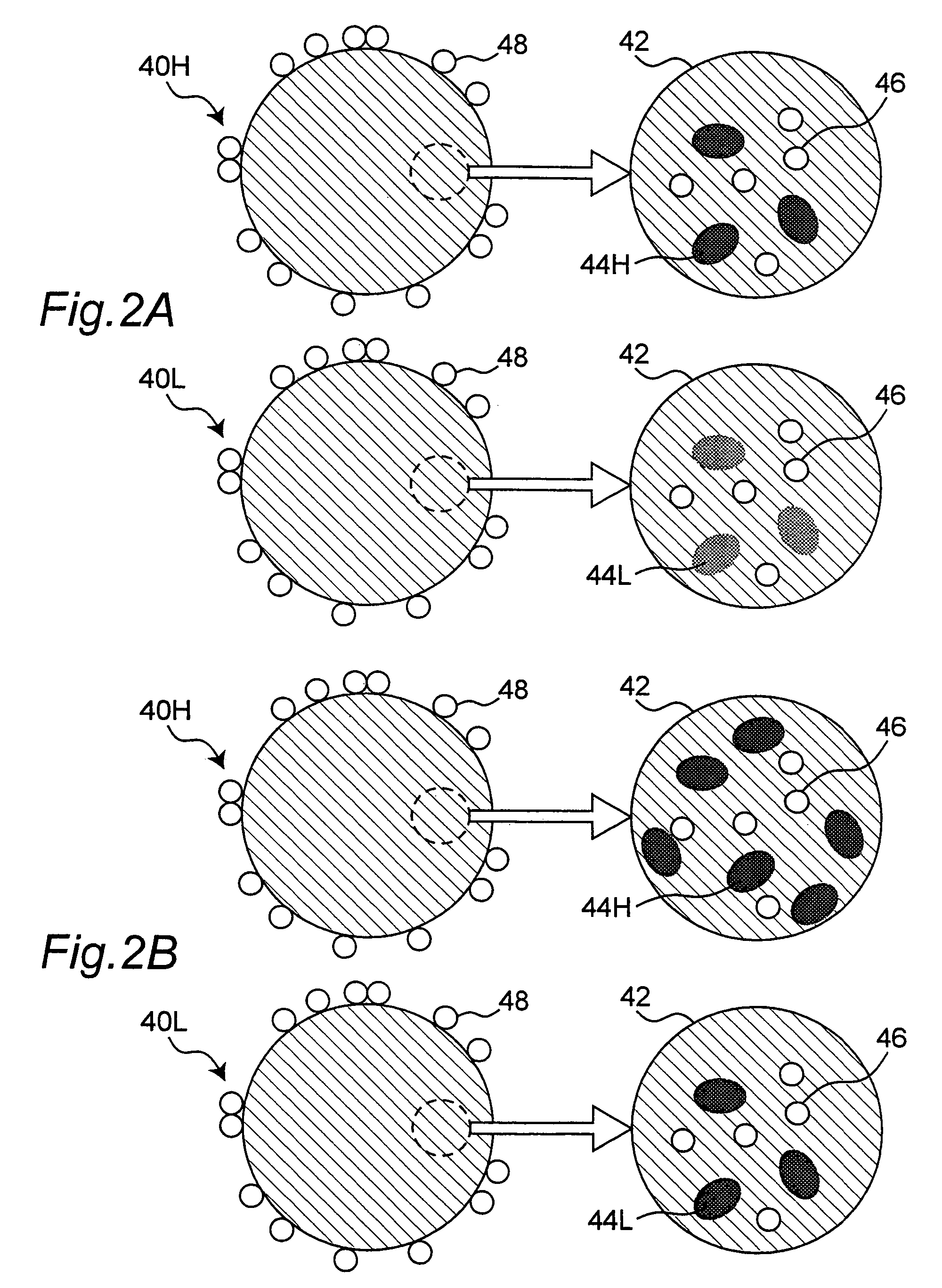
[0012]An object of the present invention is to provide an image forming apparatus suitable for controlling a mixture ratio of two or more types of toners having a generally identical hue and different reflection densities.
[0013]Another object of the present invention is to provide an image forming apparatus which enables a dead time to be reduced.
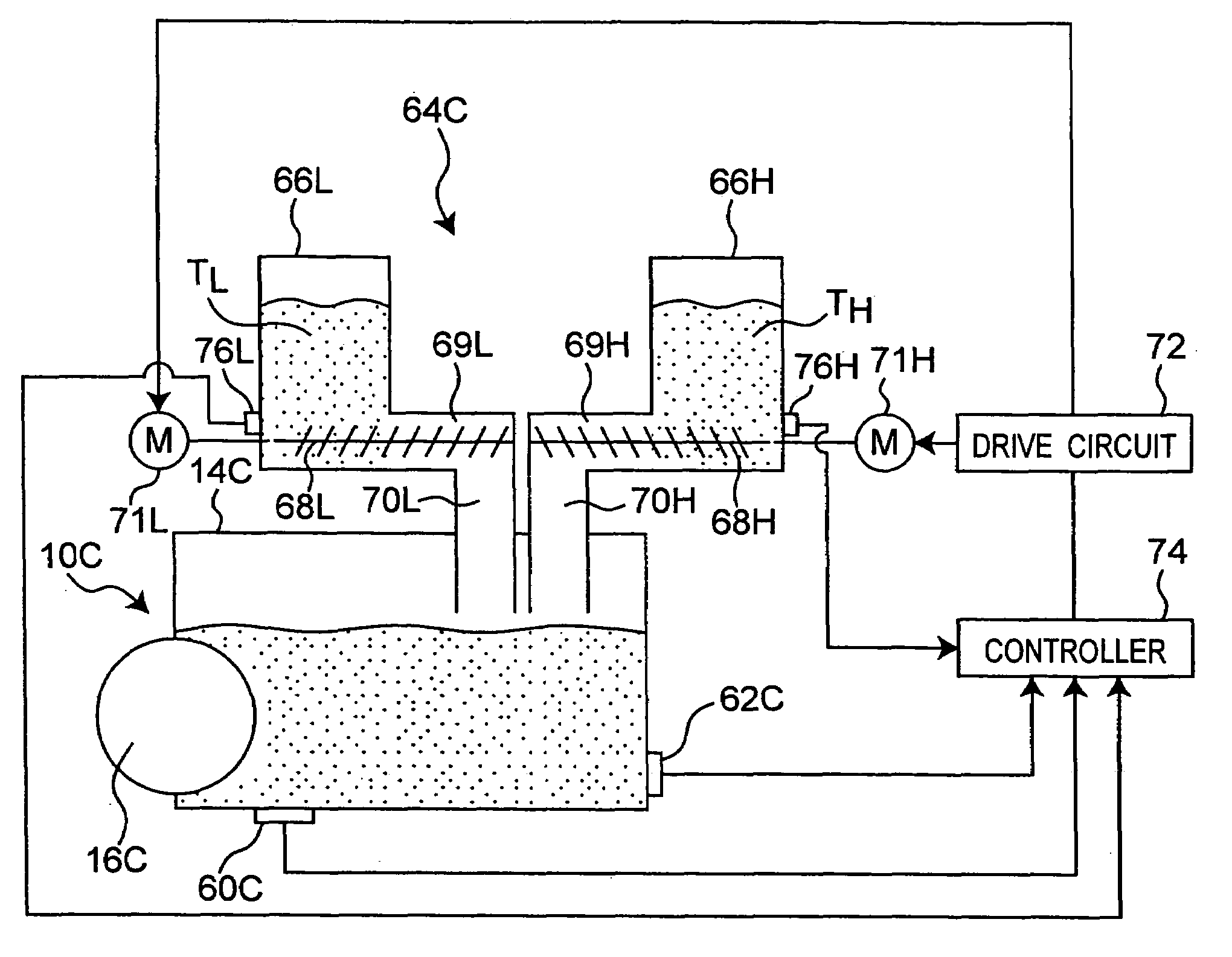
[0020]With the apparatus according to the second aspect, replenishment of toners is controlled so that a mixture ratio of the two types of toner of the mixed developer in the developer reservoir falls within a predetermined range. This allows stable and high image quality after a number of documents have been printed.
[0022]With the apparatus according to the third aspect, since each toner container accommodates one or more types of toner, replenishment of controlled amounts of one or more types of toner from each one of the toner containers allows a mixture ratio of the types of toner in the developer reservoir to be maintained within a predetermined range.

Problems solved by technology

Herein, “each of the toner containers is completely empty of toner” means that there is no sufficient amount of the toner remaining in the toner container to replenish to the developer reservoir.

Method used


Image

  • Image forming apparatus and developing unit
  • Image forming apparatus and developing unit
  • Image forming apparatus and developing unit

Examples


first embodiment

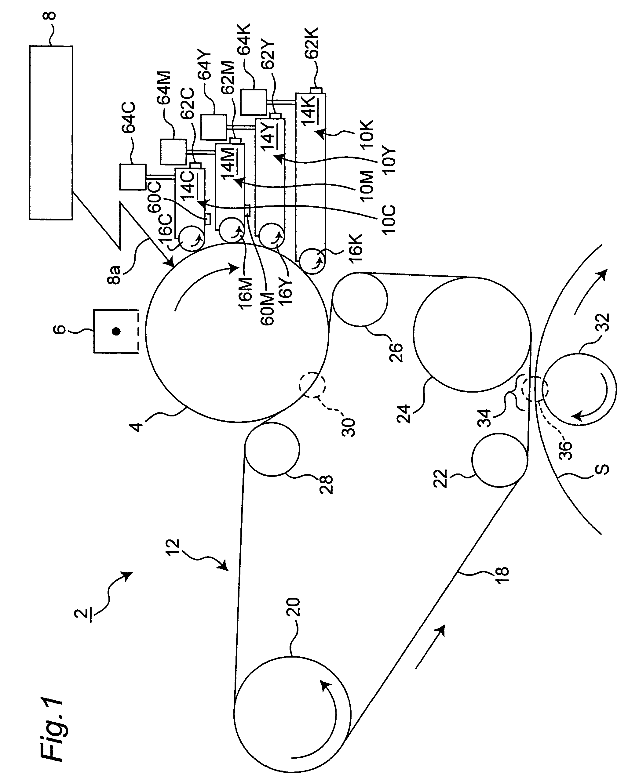
[0039]Referring to FIG. 1, there is shown a color printer, which is a first embodiment according to the present invention. The printer, generally indicated at reference number 2, includes a photoreceptor drum 4 as image bearing member for rotation in a clockwise direction of the drawing. Around the photoreceptor drum 4, a charging device 6, an exposing device 8, four developing devices 10C, 10M, 10Y and 10K and a primary transfer device 12 are positioned in this order along the rotational direction of the drum.

[0040]The charging device 6 is used for charging uniformly the surface of the photoreceptor drum 4 (the surface electric potential is V0). The exposing device 8 is used for emitting laser beam 8a selectively onto the photoreceptor drum 4 in response to image data to form a latent image on the drum.

[0041]Each of the developing devices 10C–10K is used for providing the photoreceptor drum 4 with corresponding toner to visualize the latent image. More specifically, the developing ...

second embodiment

[0088]In the first embodiment, only a lower limit of the mixture ratio of the mixed developer is taken into consideration. This means that a mixture ratio may decrease but never rises as the number of documents that have been printed is increased. More specifically, where images having many shadow areas such as character image are successively printed, consumption of the HRD toner is large. However, since the HRD and the LRD toners continue to be consumed in a ratio (weight ratio) generally identical to the mixture ratio in the developer reservoir, the mixture ratio never rises. However, where a too large amount of the LRD toner is replenished from the replenishment device to the developing device, a large amount of the LRD toner is consumed where an image with many shadow areas is formed. Thus, to suppress consumption of the LRD toner, an upper limit RH of the mixture ratio needs to be set so that controlled amount(s) of the toner(s) are replenished from the replenishment device in...


PUM


Abstract

An electrophotographic image forming apparatus includes a developing device including a developer reservoir for accommodating a mixed developer. The mixed developer includes a plurality of types of toner having a generally identical hue and different reflection densities. The apparatus also includes a replenishment device having a plurality of toner containers each accommodating one of the plurality of types of toner for replenishing the plurality of types of toner to the developer reservoir; a first detector for detecting whether each of the toner containers is completely empty of toner; and a second detector for detecting whether the developer reservoir is nearly or completely empty of mixed developer. A controller controls the replenishment device and allows or prohibits a printing operation based on the detection result of the first and the second detectors.

Description

RELATED APPLICATION[0001]This application is based on Japanese Patent Applications Nos. 2004-229100, 2004-229101 and 2004-229102, each content of which being incorporated herein by reference.BACKGROUND OF THE INVENTION[0002]1. Field of the Invention[0003]The present invention generally relates to an electrophotographic image forming apparatus such as copying machine, printer, facsimile or multifunction peripheral having functions of printing, copying, faxing and the like. More particularly, the present invention relates to an image forming apparatus that utilizes a mixed developer containing a plurality of types of toner having a generally identical hue and different reflection densities. The present invention also relates to a developing unit used in such an image forming apparatus.[0004]2. Description of the Related Art[0005]There has been known an image forming device which enables image quality of images with highlight areas to be improved and the consumption of a developer to b...

Claims


Application Information

Patent Timeline
Patent Type & Authority Patents(United States)
IPC IPC(8): G03G15/08
CPCG03G15/0856G03G15/0877G03G15/086
Inventor HIROTA, SOHTANAKA, MASAKIKOUZAKI, MASAHIROSAKATANI, KAZUOMIOBARA, MITSURU
Owner KONICA MINOLTA INC
Learn More