Check patentability & draft patents in minutes with Patsnap Eureka AI!

System and method for adaptively controlling receiver gain switch points

a wireless communication and gain switch technology, applied in the field of communication receivers, can solve the problems of affecting the selection of optimal gain and noise figure needed to recover low power received signals, often including undesired inband signals, and referred to as jammers

Inactive Publication Date: 2007-07-24
KYOCERA CORP
View PDF15 Cites 9 Cited by
  • Summary
  • Abstract
  • Description
  • Claims
  • Application Information

AI Technical Summary

Benefits of technology

This approach enhances receiver performance by optimizing the C / N ratio, improving linearity, noise figure, and gain settings, thereby increasing data communication capacity and preventing distortion associated with jammer interference.

Problems solved by technology

However, in practice, received signals often include undesired inband signals, referred to as jammers.
Jammers and inband communication signals with high power levels can cause distortion and intermodulation products when amplified.
Unfortunately, the gain reductions that are performed to minimize the creation of intermodulation products associated with jammers can work against the selection of optimal gain and noise figure needed to recover low power received signals.
As noted above, the trade off made between linearity and noise figure may limit receiver performance.
However, these limitations often prevent a receiver from being set to optimally process an intended signal.

Method used


Image

  • System and method for adaptively controlling receiver gain switch points
  • System and method for adaptively controlling receiver gain switch points
  • System and method for adaptively controlling receiver gain switch points

Examples


Embodiment Construction

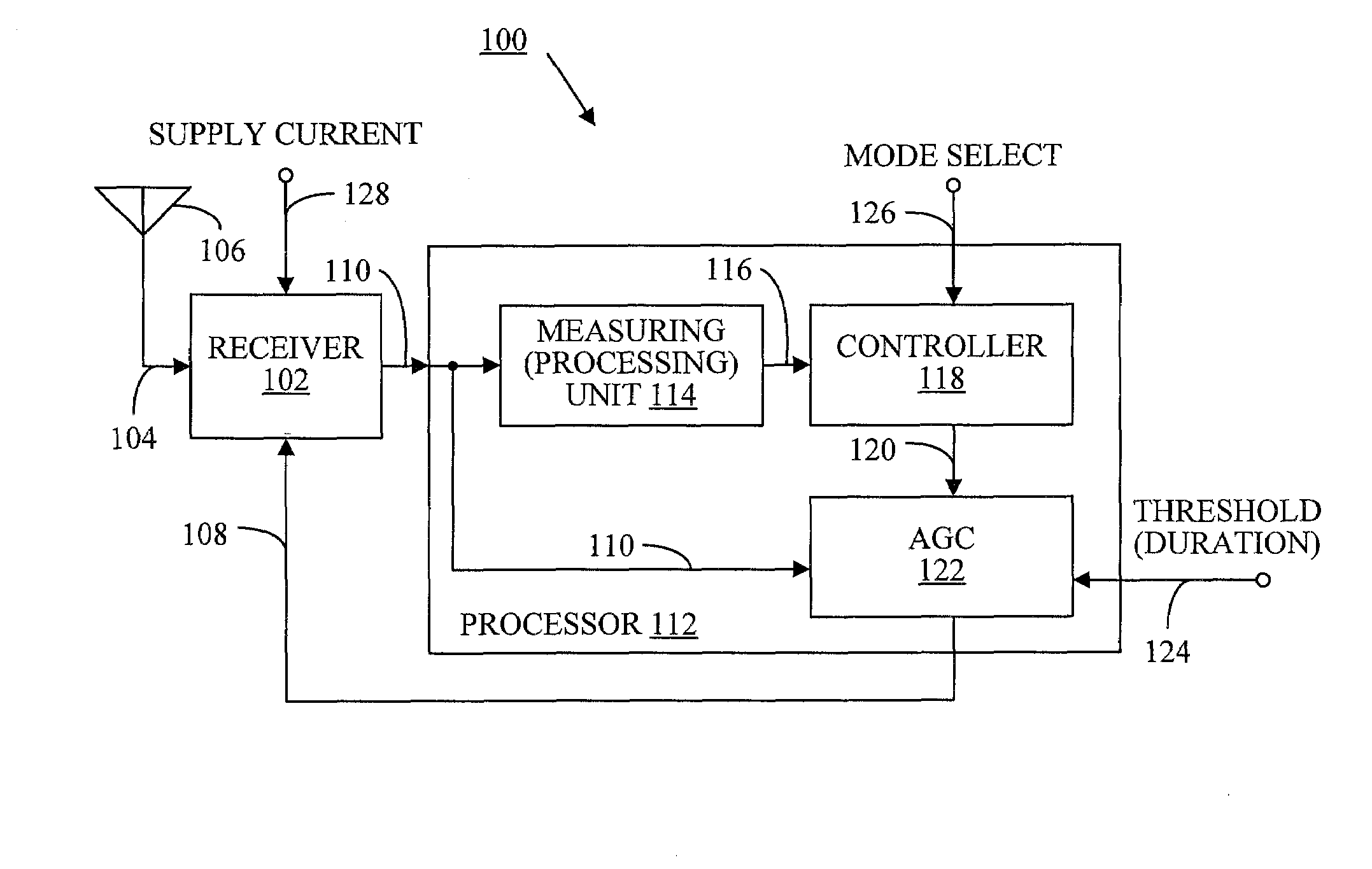
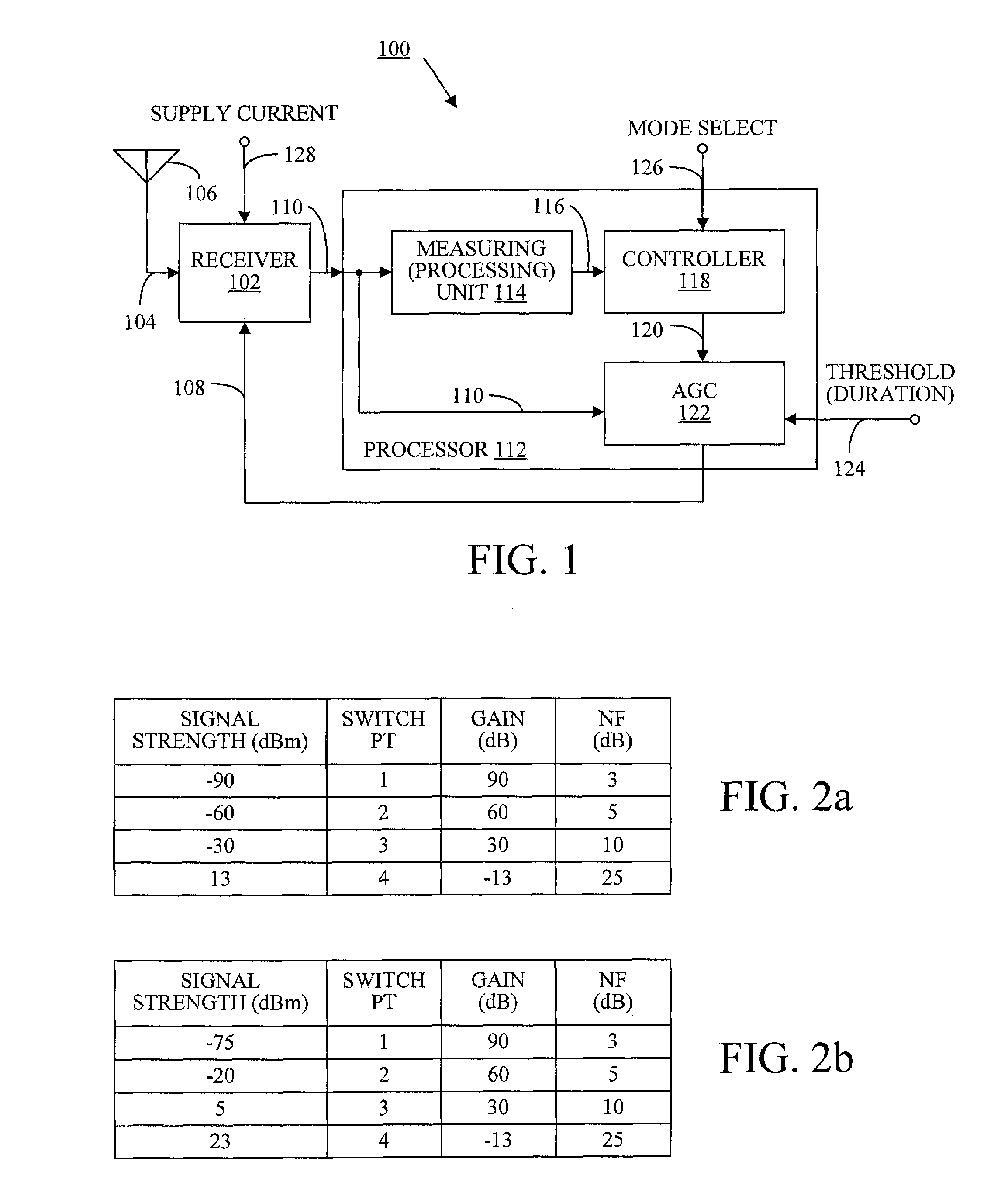
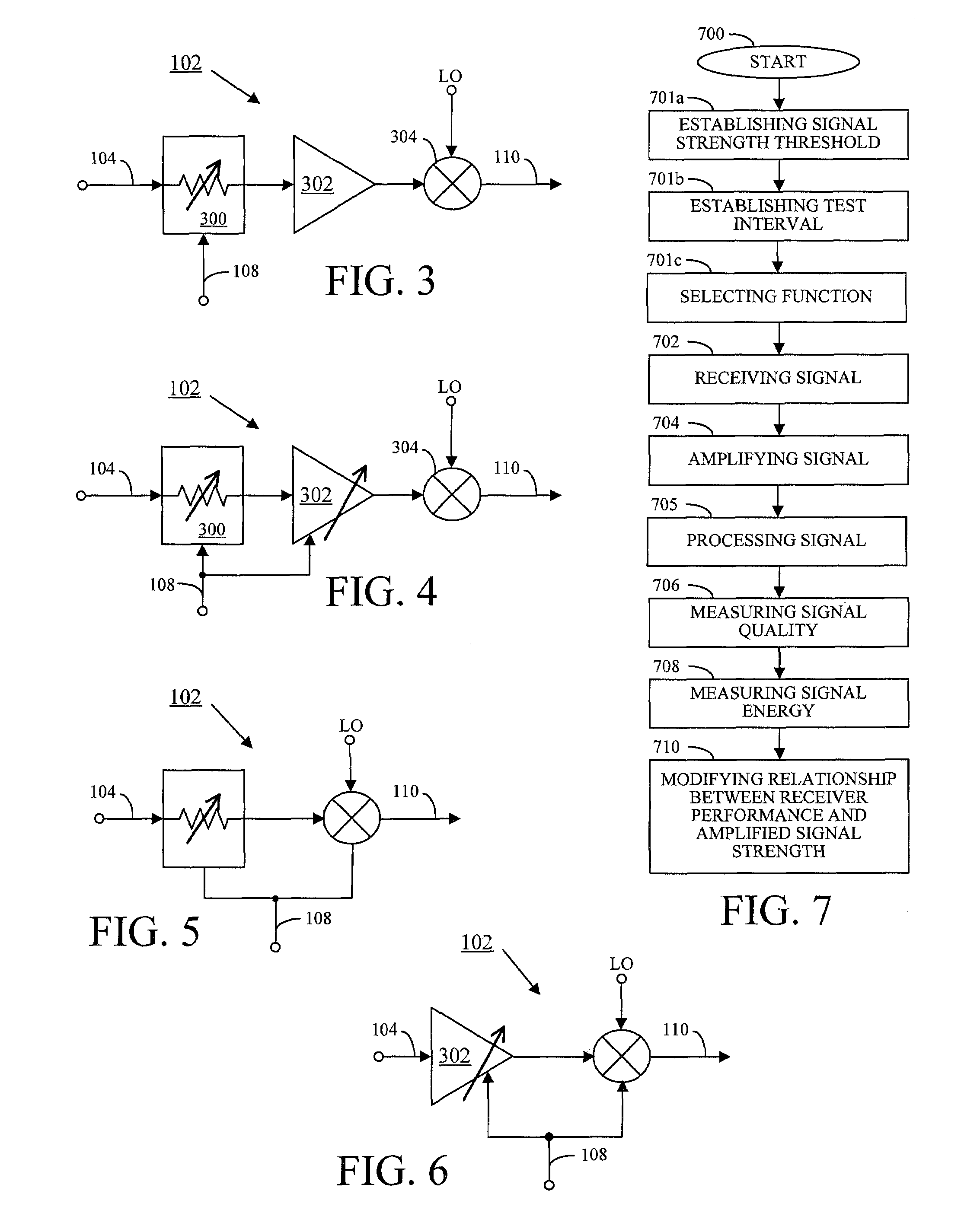
[0028]FIG. 1 is a schematic block diagram illustrating the present invention wireless communications device receiver system with adaptively controllable gain switch points. The system 100 comprises a receiver 102 having an input on line 104 to accept variable strength received signals. As shown, the signals are received on an antenna 106. As understood by one skilled in the art, other filter and transceiver switching elements (not shown) may be interposed between the antenna 106 and the receiver 102. The receiver 102 has an input on line 108 to accept gain state signals and an output on line 110 to supply a signal amplified in response to the gain state signals.

[0029]A processor 112 is shown that includes a measuring circuit 114 having an input on line 110 to accept the amplified signal. The measuring circuit 114 has an output on line 116 to supply an inband power measurement. A controller 118 has an output on line 120 to supply a control signal. The control signal is responsive to ...


PUM


Abstract

Accordingly, a system and method are provided for adaptively controlling amplification in a wireless communications device receiver. The method comprises: receiving a signal with a variable signal strength; amplifying the received signal in response to the signal strength, to supply an amplified signal. More specifically, amplifying the received signal in response to signal strength includes selecting a gain state in response to a plurality of signal strength switch point. The method further comprises: measuring signal quality; measuring signal energy; and, modifying a relationship between receiver performance and amplified signal strength, in response to the measured signal quality and measured signal energy. Other aspects of the method comprise processing the amplified signal, so that a processed signal quality and processed signal energy can be measured. Then, the relationship between receiver performance and amplified signal strength is modified in response the processed signal quality and the processed signal energy.

Description

BACKGROUND OF THE INVENTION[0001]1. Field of the Invention[0002]This invention generally relates to communication receivers and, more particularly, to a system and method for adaptively controlling the gain switch points in a wireless communications receiver.[0003]2. Description of the Related Art[0004]FIG. 8 is a schematic block diagram illustrating a conventional wireless communications receiver (prior art). Ideally, a wireless communications device receives desired, inband communication signals at appropriate power levels. However, in practice, received signals often include undesired inband signals, referred to as jammers. Further, the receiver must have an adjustable gain to create appropriate power level signals for subsequent processing and demodulation. Jammers and inband communication signals with high power levels can cause distortion and intermodulation products when amplified. The linearity of, and conversely, the distortion in the receiver can be measured by the third o...

Claims


Application Information

Patent Timeline
Patent Type & Authority Patents(United States)
IPC IPC(8): H04B1/06H03G3/20H03G3/30
CPCH03G3/3052H03G3/3078
Inventor WALLACE, RAYCORN, ED
Owner KYOCERA CORP
Features
  • R&D
  • Intellectual Property
  • Life Sciences
  • Materials
  • Tech Scout
  • Unparalleled Data Quality
  • Higher Quality Content
  • 60% Fewer Hallucinations
Learn More