Apparatus for the control of brakes in bicycles and the like

a technology for bicycles and brakes, applied in mechanical braking transmission, braking systems, transportation and packaging, etc., can solve problems such as injury to users, and achieve the effects of reducing overall dimensions, reducing costs, and increasing compactness

Inactive Publication Date: 2007-07-31
FORMULA
View PDF12 Cites 30 Cited by
  • Summary
  • Abstract
  • Description
  • Claims
  • Application Information

AI Technical Summary

Benefits of technology

[0006]The advantages of the present invention are that the apparatus has extremely limited overall dimensions and, therefore, gives the handlebar a greater compactness; that the presence of a hydraulic brake makes it possible to use the levers originally present on the bicycle, that is, those for brakes op...

Problems solved by technology

A drawback of the brake-controlling devices is due the fact that the brake pump, with relevant accessories, is applied to the handlebar, thereby constituting a separate element.
This...

Method used


Image

  • Apparatus for the control of brakes in bicycles and the like
  • Apparatus for the control of brakes in bicycles and the like
  • Apparatus for the control of brakes in bicycles and the like

Examples


Embodiment Construction

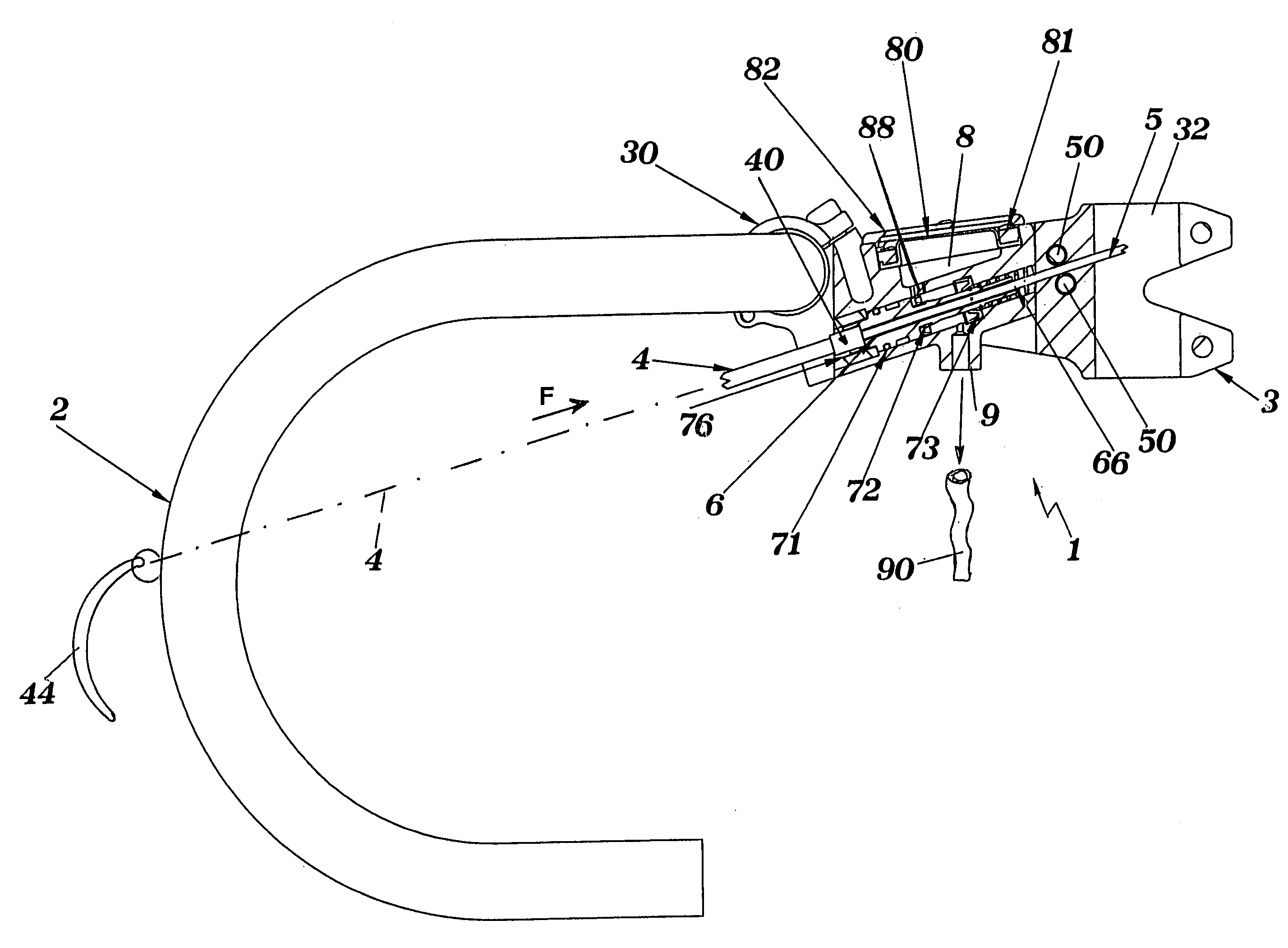
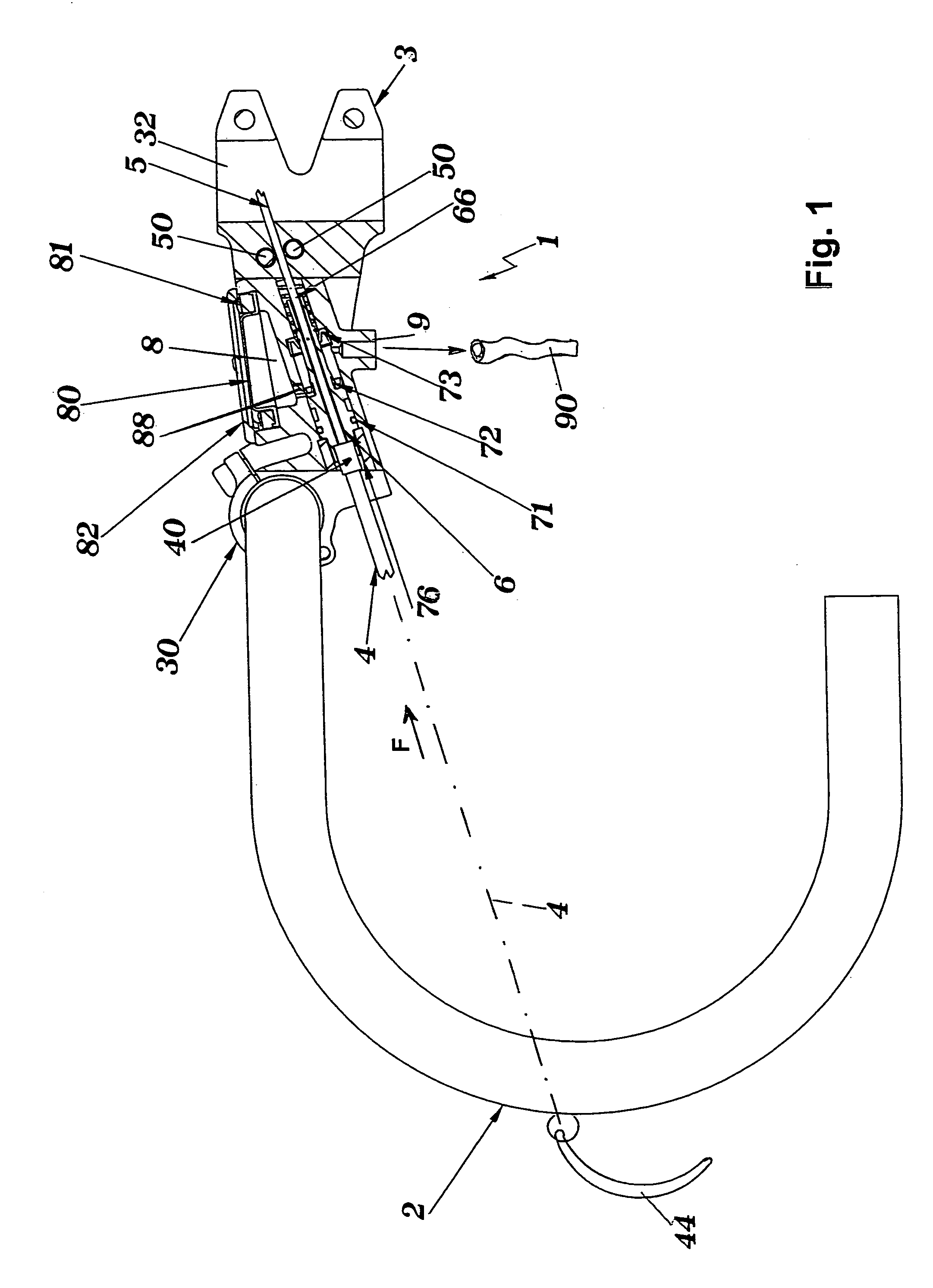
[0012]In its general form, the basic characteristic of an apparatus for the control of brakes according to the invention, is that the said apparatus is held within a portion of the handlebar, or a part associated therewith such as, for example, a connecting lug or other similar elements.

[0013]Referring in particular to FIG. 1, an apparatus 1 for the control of brakes according to the present invention, is fitted within the lug 3 which defines the connection between the handlebar 2 and the sleeve (not shown).

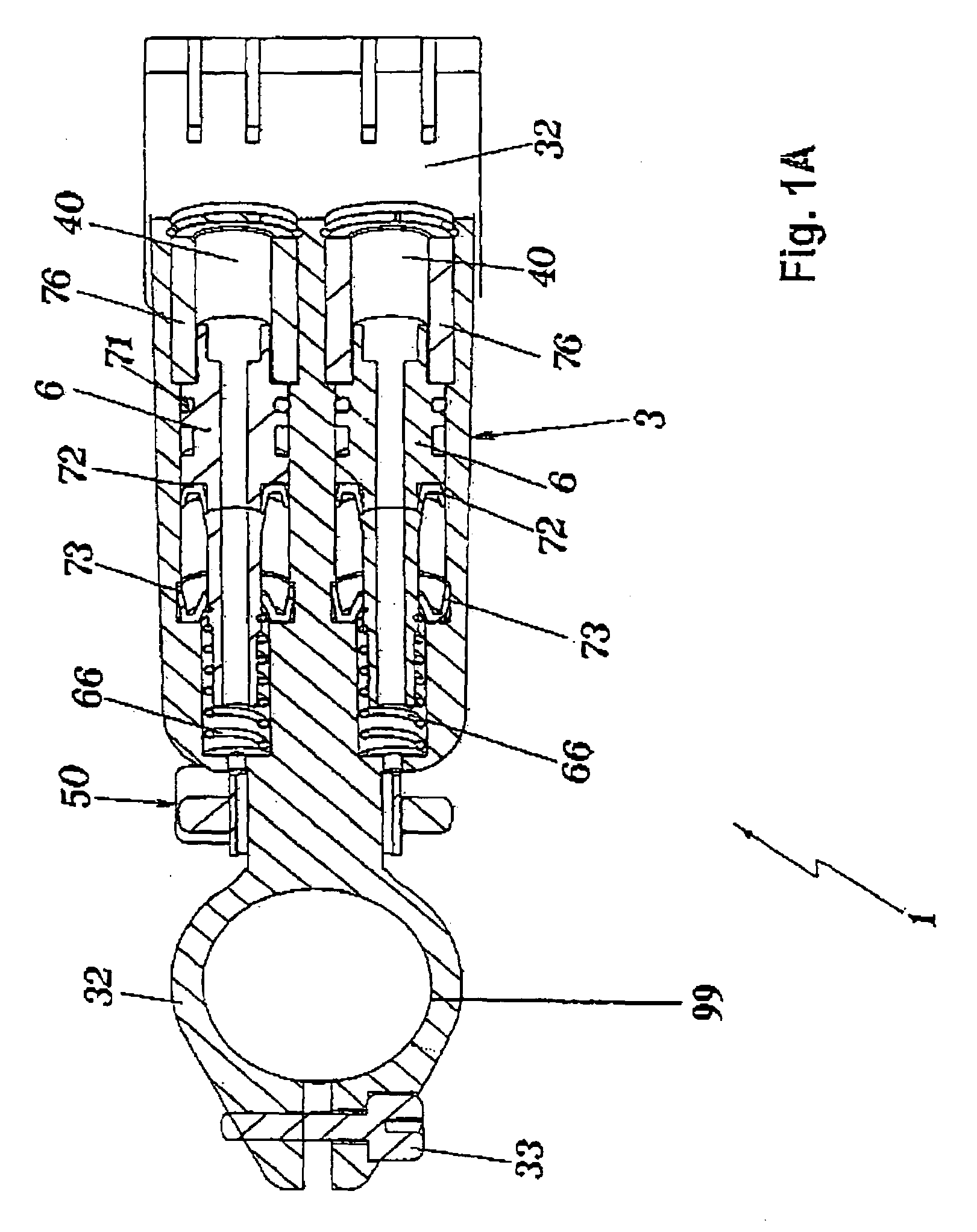
[0014]In particular, the lug 3 has first clamping means 30, 31 which allow fixing the apparatus 1 to the body of the handlebar 2, and second clamping means 32, 33 to be fixed to the steering stem 99 to be inserted into the sleeve. The clamping means consists of clamps 30 and 32 made up of two bodies joined by respective screws 31 and 33 in a manner known per se.

[0015]Provided inside the body of the lug 3 is a reservoir 8 for the oil of the hydraulic circuit operating the brake. I...


PUM


Abstract

The invention refers to an apparatus for the control of brakes in bicycles and the like, to be used, in particular, for disc brakes mounted on bicycles and comprising a pump able to push fluid into a hydraulic circuit connected to the brake, characterized in that the pump is held inside the handlebar or a part associated therewith.

Description

[0001]The present invention refers to an apparatus for the control of brakes, in bicycles and the like, to be used, in particular, for disc brakes mounted on bicyclesBACKGROUND OF THE INVENTION[0002]It is known that the action exerted upon the brake's lever is transmitted to a calliper acting on the disc through a hydraulic connection associated with a pump to urge the same calliper acting on the disc.[0003]A drawback of the brake-controlling devices is due the fact that the brake pump, with relevant accessories, is applied to the handlebar, thereby constituting a separate element. This characteristic may result unsuitable owing to the fact that the handlebar has larger dimensions, the brake pump can be damaged by possible strokes, and may hurt the user in case of falls.SUMMARY OF INVENTION[0004]The object of the present invention is to overcome the above drawbacks.[0005]This result has been achieved, according to the invention, by adopting the idea of making an apparatus having the...

Claims


Application Information

Patent Timeline
IPC IPC(8): B60T11/00B60T11/04B60T11/10B60T11/20B62K19/38B62K21/12B62L3/02
CPCB60T11/046B60T11/102B60T11/20B62K19/38B62K21/12B62L3/023
Inventor BECOCCI, ANDREA FIORENZOBECOCCI, FRANCESCO
Owner FORMULA
Why Eureka
Try Eureka