Table pad coupling system

a technology for coupling systems and tables, applied in the field of table pads, can solve problems such as inability to coupling, and achieve the effect of increasing the magnetic coupling between two magnets

Inactive Publication Date: 2007-07-31
OHIO TABLE PAD COMPANY THE
View PDF12 Cites 35 Cited by
  • Summary
  • Abstract
  • Description
  • Claims
  • Application Information

AI Technical Summary

Benefits of technology

[0012]An advantage of the present invention is that an otherwise symmetric table pad can be oriented in different manners and still provide magnetic coupling between table pads.
[0013]Another advantage of the present invention is that one table pad is provided having a magnetic orientation that is opposite to an adjacent table pad thereby increasing the magnetic coupling of two magnets located in adjacent table pads.

Problems solved by technology

A problem with the prior art method is that if table pads 12 and 14 are positioned on a tabletop such that the two iron pieces are proximate each other, no coupling occurs.

Method used


Image

  • Table pad coupling system
  • Table pad coupling system
  • Table pad coupling system

Examples


Embodiment Construction

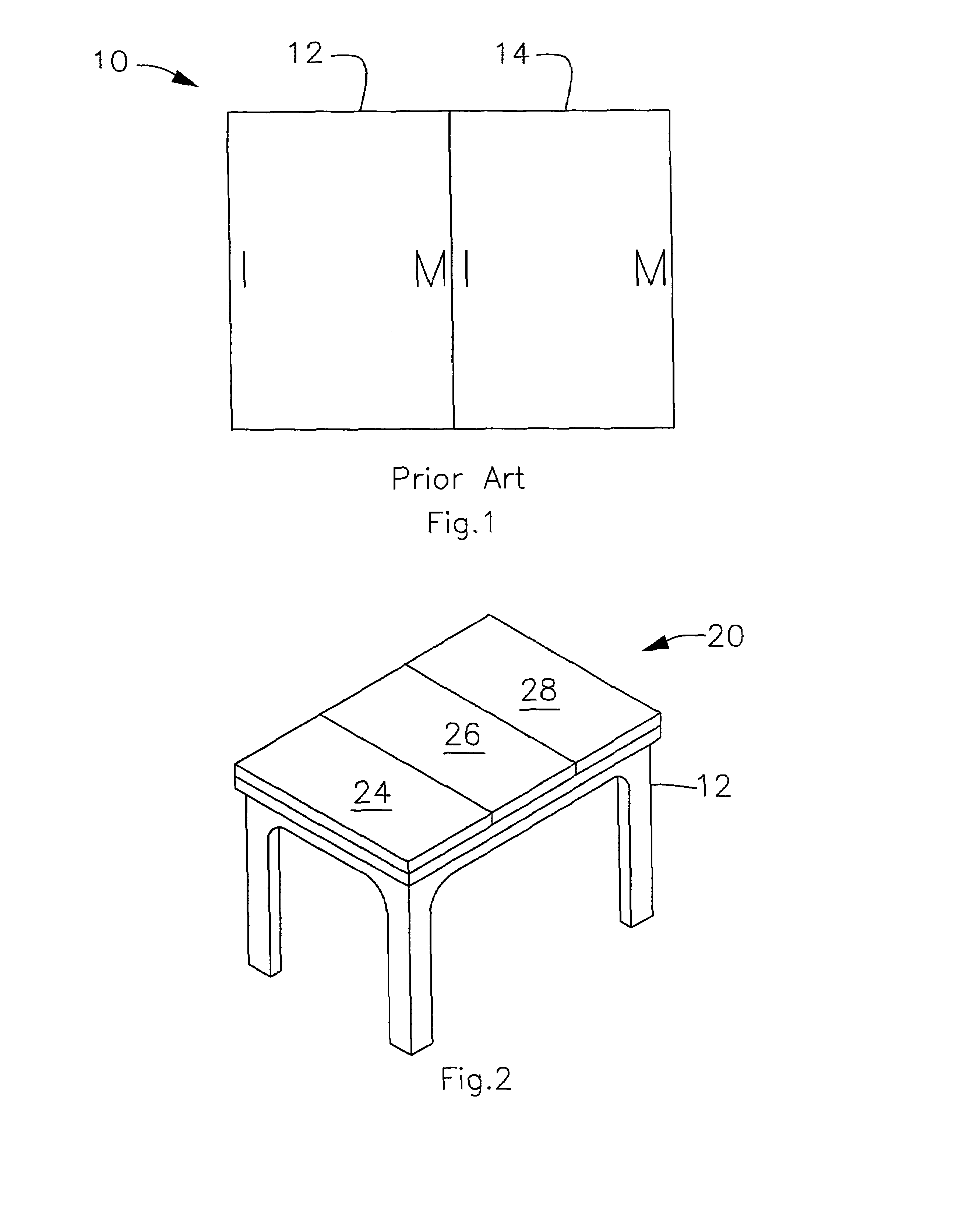
[0025]Referring now to the drawings, and, more particularly to FIG. 2, there is shown a table pad assembly 20 of the present invention, including table pads 24, 26 and 28 positioned upon table 22. Although, as shown in FIG. 2, table pads 24, 26 and 28 are substantially similar in shape and size, it is understood that table pads 24, 26 and 28 may vary in shape and relative size. The contacting edges between pad 24 and 26 and between 26 and 28 are shown as substantially straight lines. While this is often the case, it is not to be construed that only straight interfaces have been contemplated by the present invention.

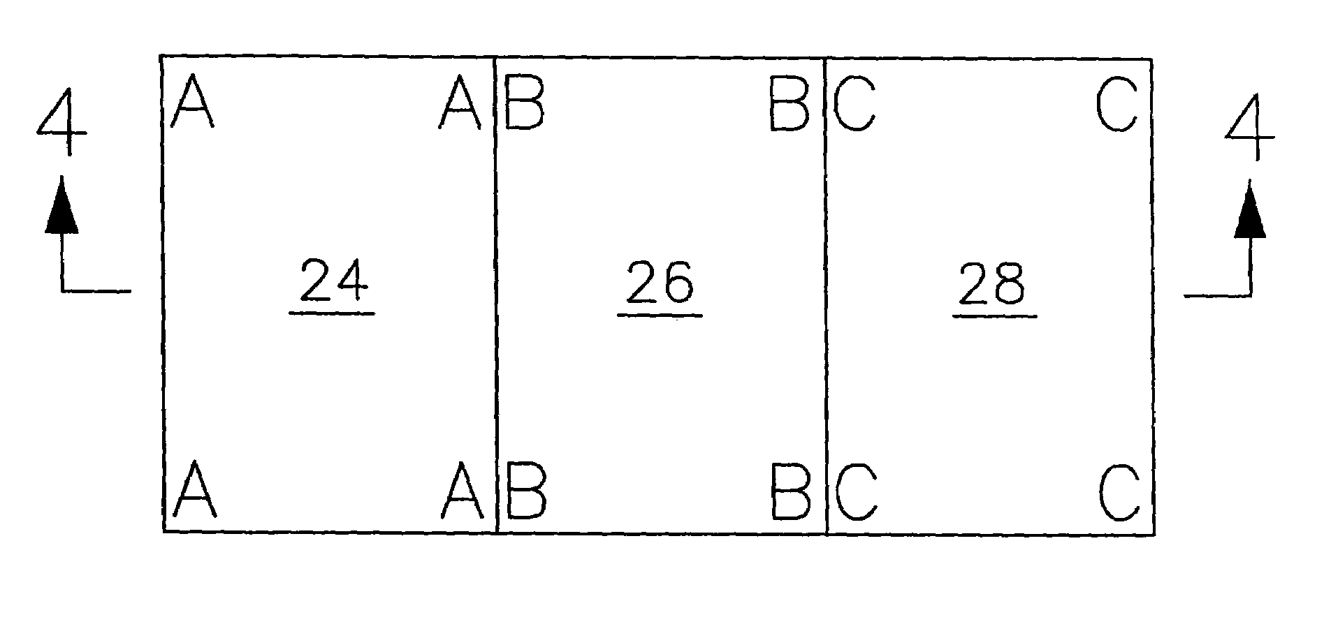
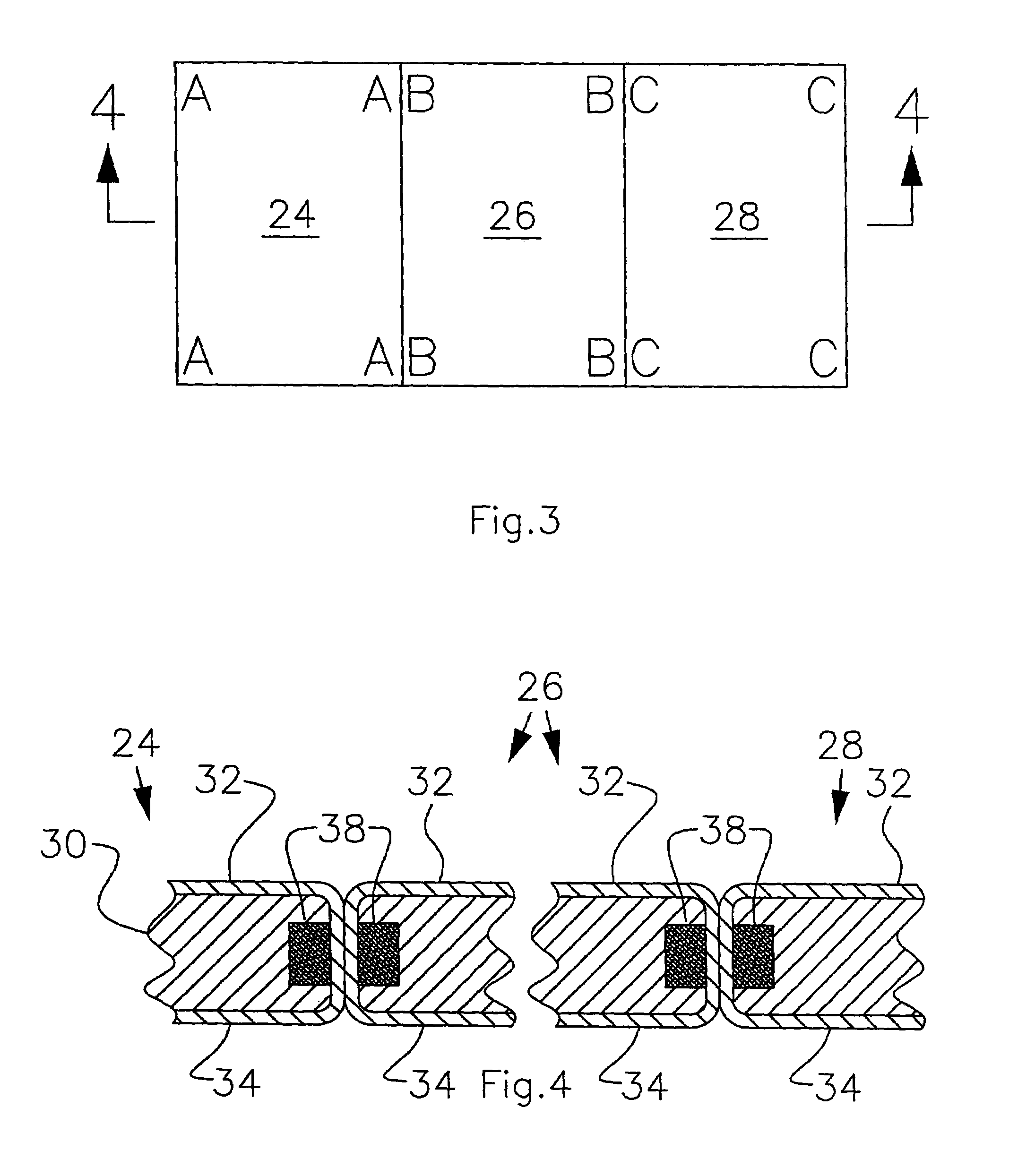
[0026]Now, additionally referring to FIGS. 3-6, there is illustrated a configuration system for the table pads of the present invention. It should be noted that each table pad 24, 26 and 28 each have letters, illustrated in FIG. 3, which correspond to the type of coupler 38 that is located within each table pad. Table pads 24, 26 and 28 include a core 30, an upper surface...


PUM

PropertyMeasurementUnit
magnetic polarityaaaaaaaaaa
sizesaaaaaaaaaa
magneticaaaaaaaaaa

Abstract

A table pad coupling system including a first table pad and a second table pad. The first table pad having a plurality of peripheral surfaces including a first peripheral surface and a second peripheral surface, the first peripheral surface opposite the second peripheral surface. The first table pad additionally including a plurality of magnets positioned within the first table pad, the plurality of magnets including a first magnet associated with the first peripheral surface and a second magnet associated with the second peripheral surface, the first and second magnets having a surface of a same magnetic polarity, the surface of the first magnet and the surface of the second magnet outwardly oriented proximate the respective first and second peripheral surfaces. The second table pad having a plurality of peripheral surfaces including a first peripheral surface and a second peripheral surface, the first peripheral surface opposite the second peripheral surface, the first peripheral surface of the first table pad disposed adjacent the first peripheral surface of the second table pad.

Description

[0001]This is a continuation of application Ser. No. 11 / 077,482 filed Mar. 10, 2005, now U.S. Pat. No. 7,018,693 issued Mar. 28, 2006, which is a continuation of application Ser. No. 10 / 682,065 filed Oct. 9, 2003 now U.S. Pat. No. 6,919,116 issued Jul. 19, 2005.BACKGROUND OF THE INVENTION[0002]1. Field of the Invention[0003]The present invention relates to a table pad, and, more particularly, to a method and a system for assembling table pads on a tabletop.[0004]2. Description of the Related Art[0005]Table pads for the protection of tabletops are known in the art and are available from many sources. Table pads are manufactured to standard sizes, as well as custom sizes, primarily for the protection of wooden tabletops. Table pads normally have a cushioned or soft bottom surface for contact with the tabletop and a harder, more resilient often water resistant outer upper surface to resist heat and moisture damage that may occur from spills and the setting of hot dishes thereon.[0006]T...

Claims


Application Information

Patent Timeline
Patent Type & Authority Patents(United States)
IPC IPC(8): B32B3/06
CPCA47G11/006Y10S428/90Y10T428/192Y10T428/18Y10T428/24777
Inventor HEAL, GARY W.KRAUSER, CHRISTOPHER P.
Owner OHIO TABLE PAD COMPANY THE
Why Eureka
Try Eureka