Control circuit of DC-DC converter and its control method

a control circuit and converter technology, applied in the direction of electric variable regulation, process and machine control, instruments, etc., can solve the problems of power supply excess, power loss in the bleeder resistance, and the inability to improve the power conversion efficiency of light load, so as to achieve the effect of improving the power conversion efficiency

Active Publication Date: 2007-07-31
CYPRESS SEMICON CORP
View PDF4 Cites 19 Cited by
  • Summary
  • Abstract
  • Description
  • Claims
  • Application Information

AI Technical Summary

Benefits of technology

[0014]The invention is intended to solve at least one of the problems of the background art, and it is hence an object thereof to present a control circuit of DC-DC converter capable of improving the control voltage of output voltage and improving the power conversion efficiency at light load in a DC-DC converter of synchronous rectifying system, and its control method.
[0035]Accordingly, when the PWM fixed control is selected, the non-conductive control of the second switching element or second current path is suppressed, and it is allowed to invert the current direction of the first current, and hence at light load, switching action is performed at predetermined period by PWM system, and if excess power is discharged to the load side in every period, the excess power can be returned to the inductive element in every period, and excessive elevation of output voltage is suppressed, and it is maintained within a control voltage. At this time, it is hence not necessary to use dummy load such as bleeder resistance at the load side, without being accompanied by additional power consumption, and the excess power returned to the inductive element can be regenerated at the input side, so that the power conversion efficiency can be enhanced.

Problems solved by technology

In the DC-DC converter shown in the background art, however, when the supply power is larger than the load power at light load, the power supply is excess.
However, regardless of the magnitude of load power, a power loss occurs in the bleeder resistance as a fixed power loss, and in particular the power conversion efficiency at light load cannot be improved.

Method used


Image

  • Control circuit of DC-DC converter and its control method
  • Control circuit of DC-DC converter and its control method
  • Control circuit of DC-DC converter and its control method

Examples


first embodiment

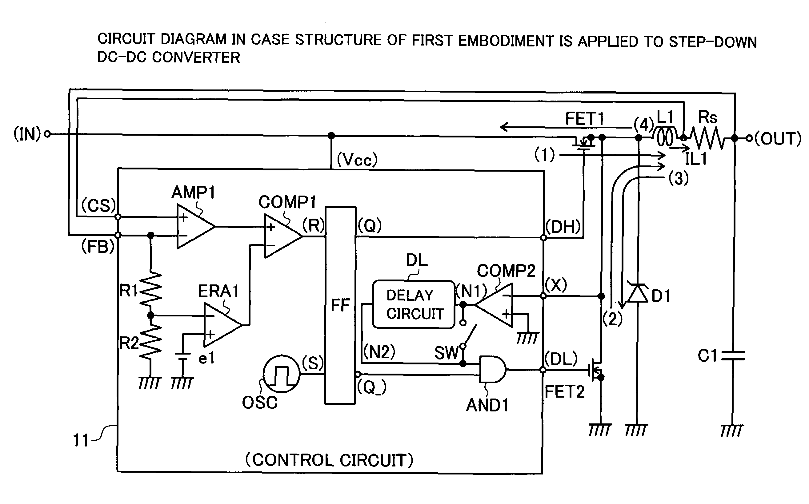
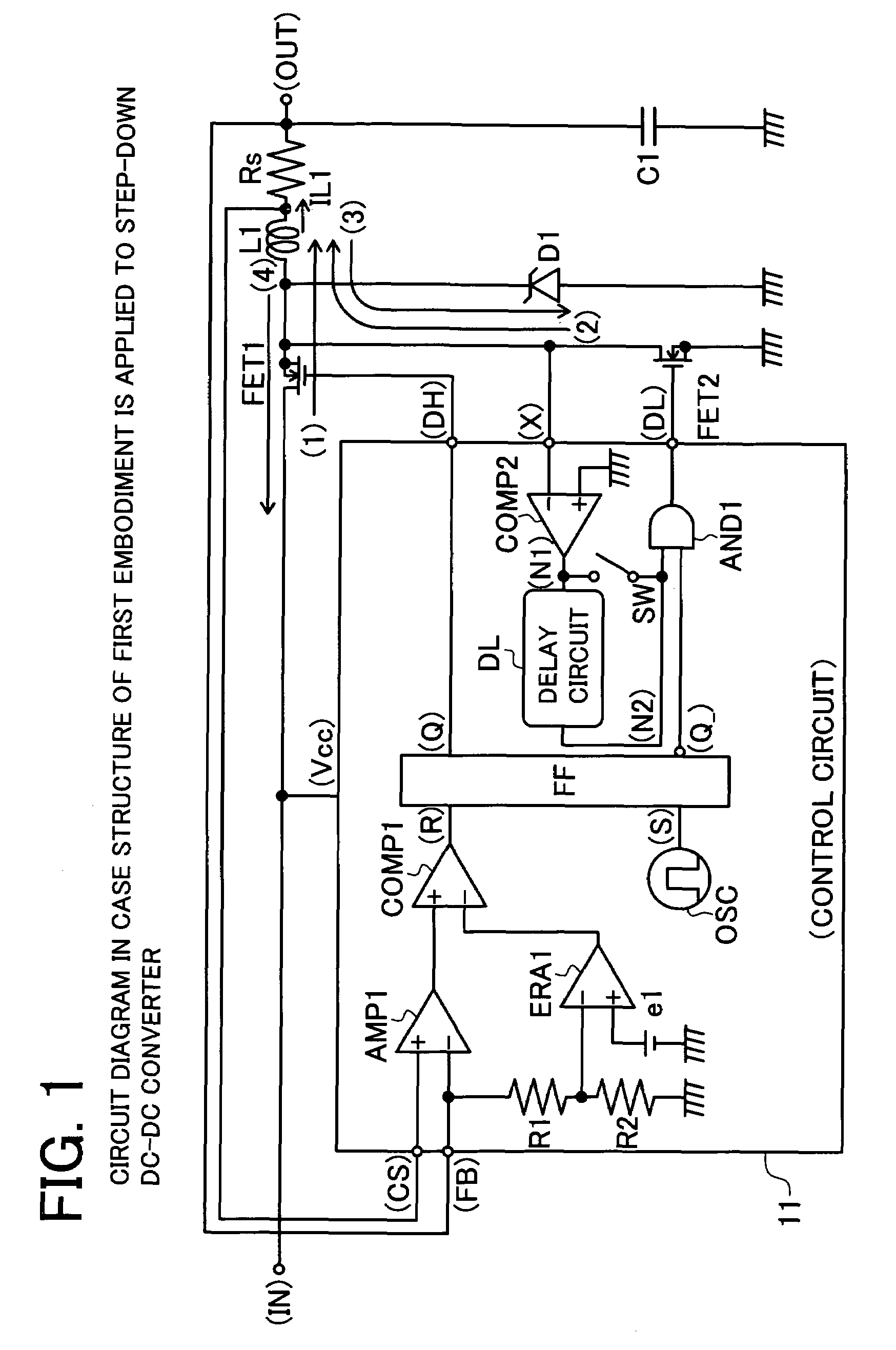
[0047]FIG. 1 is a circuit diagram of a first embodiment applied in a step-down DC-DC converter. The non-conductive timing of synchronous transistor which conducts when discharging an electric power to the load is delayed from the zero timing of discharge current toward the load after completion of power discharge. For the delayed period, the synchronous transistor is maintained in conductive state, and the discharge current is inverted, and the load side excess power is returned.

[0048]An input terminal (IN) in which input voltage VIN is supplied is connected to a drain terminal of NMOS transistor FET1. A source terminal of the NMOS transistor FET1 is connected to one terminal of choke coil L1 and a drain terminal of NMOS transistor FET2. A source terminal of the NMOS transistor FET2 is connected to a grounding potential. Gate terminals of the NMOS transistors FET1, FET2 are respectively connected to output terminals (DH), (DL) of a control circuit 11 which is described later. A diod...

second embodiment

[0078]FIG. 4 is a circuit diagram of a second embodiment applied in a step-down DC-DC converter. The non-conductive timing of synchronous transistor conducting when discharging electric power to the load can be set as the timing of returning the load side excess power by inversion of the discharge current by setting offset in the detection of discharge current. By addition of offset, the non-conductive transition of synchronous transistor is delayed, and the load side excess power is returned.

[0079]In a control circuit 12 shown in FIG. 4, instead of the switch circuit SW and delay circuit DL in the control circuit 11 in FIG. 1, switch circuit SW2 and offset unit e2 are provided. At the input terminal of the AND gate circuit AND1, an output terminal of comparator COMP2 is connected instead of output terminal (N2) of delay circuit DL. Other circuit configuration is same as in FIG. 1, and the explanation is omitted.

[0080]The switch circuit SW2 connects either grounding potential or off...

third embodiment

[0084]FIG. 5 is a circuit diagram of a third embodiment applied in a step-down DC-DC converter. In a DC-DC converter capable of selecting the PWM fixed control and PWM / PFM variable control, the conduction control of synchronous transistor is made non-conductive by preventing counterflow of coil current by having rectifying action in the PWM / PFM variable control, and the counterflow of coil current is permitted and conductive state is maintained in the PWM fixed control. In the PWM fixed control for supplying power to the load side in every period, it is composed to return the load side excess power in every period.

[0085]In a control circuit 13 shown in FIG. 5, instead of the switch circuit SW and delay circuit DL in the control circuit 11 in FIG. 1, an OR gate circuit OR1 is provided. An input terminal of OR gate circuit OR1 is connected to an output terminal of comparator COMP2, and receives selection signal DSA of PWM fixed control. The selection signal DSA is a signal which is hi...


PUM


Abstract

In a DC-DC converter of synchronous rectifying system, a control circuit of DC-DC converter capable of improving the control voltage value of output voltage at light load and enhancing the power conversion efficiency, and its control method are presented. An inverting input terminal of comparator COMP2 of which non-inverting input terminal is connected to a grounding potential is connected to one terminal of choke coil L1 by way of terminal (X). An output terminal (N1) of comparator COMP2 is connected to a delay circuit DL, and an output terminal (N2) of delay circuit DL is connected to AND gate circuit AND1. The delay circuit DL is a circuit for delaying the transition from high level to low level of input terminal (N1). Excessive power supplied more than demanded by the load at light load is returned to choke coil L1. Elevation of output voltage VOUT due to excess power accumulated in output capacitor C1 can be suppressed.

Description

CROSS-REFERENCE TO RELATED APPLICATIONS[0001]This application is based upon and claims the benefit of priority from the prior Japanese Patent Application No. 2004-187918 filed on Jun. 25, 2004, the entire contents of which are incorporated herein by reference.BACKGROUND OF THE INVENTION[0002]1. Field of the Invention[0003]The present invention relates to control of DC-DC converter, and more particularly to control at light load in DC-DC converter of synchronous rectifying system.[0004]2. Description of the Related Art[0005]A personal digital assistant operates on battery power, but along with power consumption by continued operation of the device, the battery power is consumed and the battery output voltage declines with the passing of the time. In order to maintain a constant voltage level of the device power source in spite of such time course changes of the battery voltage, the supply voltage is stabilized by a DC-DC converter.[0006]The DC-DC converter used in the personal digita...

Claims


Application Information

Patent Timeline
Patent Type & Authority Patents(United States)
IPC IPC(8): G05F1/40H02M3/158H02M3/155
CPCH02M3/1588H02M2001/0032Y02B70/1466Y02B70/16Y02B70/10H02M1/0032H02M3/155
Inventor YASUKOUCHI, KATSUYUKIITO, HIDENOBU
Owner CYPRESS SEMICON CORP
Why Eureka
Try Eureka