Projection screen and method for manufacturing the same

a technology of projection screen and projection screen, which is applied in the field of projection screen, can solve the problems of inflexibility of the screen, difficulty in improving the luminous contrast of the screen, and requiring time and work, so as to reduce the reflection of extraneous light, and improve the low contrast of the image formed on the projection screen

Inactive Publication Date: 2007-07-31
SONY CORP
View PDF13 Cites 5 Cited by
  • Summary
  • Abstract
  • Description
  • Claims
  • Application Information

AI Technical Summary

Benefits of technology

[0014]Accordingly, the projection screen of the present invention can selectively reflect light in the particular wavelengths and suppress reflection of extraneous light as compared to ordinary screens. Thus, the low contrast of an image formed on the projection screen is improved and reflection of extraneous light is effectively reduced, resulting in bright images. Even if the projection screen is used in a bright environment, it can provide clear images regardless of the brightness of the environment where the projection screen is used.
[0015]Designing of the optical thin film is a critical factor to achieve the aforementioned functions. For example, the optical thin film is composed of dielectric multilayers where high-refraction layers and low-refraction layers are alternately laminated. Each of the dielectric multilayers is designed by simulation based on a matrix method such that the optical thin film reflects light in particular wavelength ranges and substantially transmits light except the light in the particular wavelength ranges, thereby obtaining the above-mentioned effects.
[0018]The projection screen according to the present invention, besides including the optical thin film, which functions as a band-pass filter, preferably includes a light diffusion layer on the outermost layer of the optical thin film or in the optical thin film as an interlayer. The light diffusion layer diffuses the light reflected by the optical thin film to generate diffused light. Without the provision of the light diffusion layer, a viewer perceives only a specular reflection component as a reflected light from the projection screen. When the reflected light is composed of only the specular reflection component, there are disadvantages for the viewer such as an unclear image and a limited field of view. On the other hand, the light diffusion layer enables the viewer to perceive the diffused light, thereby greatly improving a field of view. Accordingly, the viewer can enjoy natural images.

Problems solved by technology

However, unlike self-luminescent displays and rear projectors, the front projector described above exhibits a problem in that it cannot reduce reflection of extraneous light with, e.g., an ND filter, whereby enhancement of the luminous contrast on the screen is difficult.
However, pattern formation and partial coating require time and work.
Furthermore, although screens should preferably be flexible for easy storage, this screen has no flexibility.
Simply increasing the reflectance of the screen allows not only the projected light but also the extraneous light to be well reflected, resulting in deterioration of the perceived image.
Hence, it is difficult to obtain a clear image in a bright environment.

Method used


Image

  • Projection screen and method for manufacturing the same
  • Projection screen and method for manufacturing the same
  • Projection screen and method for manufacturing the same

Examples


example

[0105]The present invention will now be described in more detail by referring to a specific example. The present invention is not restricted to the following example and may be modified within the scope of the present invention.

[0106]With the example, a projection screen according to the present invention was constructed as a grating projection screen with an optical thin film functioning as a band-pass filter for narrow-band, three-primary-color light. This grating projection screen may be employed in the above-described grating projector in FIG. 3, for example.

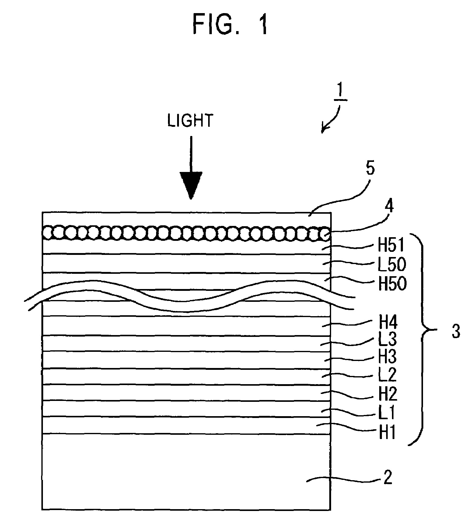
[0107]A screen substrate 62 composed of black PET with a thickness of 188μm was prepared as a screen substrate and on one surface of the screen substrate 62, an optical thin film 63 composed of dielectric multilayers was formed, thereby completing a grating projection screen 61.

[0108]The optical thin film 63 was composed of dielectric multilayers. Specifically, as shown in FIG. 8, high-refraction layers H101-H151 and low-ref...


PUM


Abstract

A projection screen and method of manufacturing provides clear images regardless of the brightness of the environment within which the projection screen is used. The projection screen includes an optical thin film comprised of a multilayer dielectric having alternating high reflectance layers for light in a particular wavelength and high transmittance for visible light except in particular wavelength ranges. The thickness of each of the dielectric multilayer is determined so that the optical thin film forms a band-pass filter.

Description

[0001]This application claims priority to Japanese Patent Application Number JP2002-070799, filed Mar. 14, 2002, which is incorporated herein by reference.TECHNICAL FIELD[0002]The present invention relates to projection screens, more particularly to a projection screen which enables an image of projected light from a projector to be well perceived even in a bright environment.BACKGROUND ART[0003]These days, overhead projectors and slide projectors are widely used when speakers present their materials in conferences or the like. Video projectors and motion film projectors employing liquid crystal displays are also becoming popular for home applications. Typically, these projectors optically modulate light from light sources via transparent liquid crystal display panels into image-forming light and emit this image-forming light through optical systems such as lenses, thereby projecting the emitted image-forming light onto screens.[0004]For example, a front projector which can form col...

Claims


Application Information

Patent Timeline
Patent Type & Authority Patents(United States)
IPC IPC(8): G03B21/60G02B1/10G02B5/02G02B5/20G03B21/56
CPCG02B5/0242G02B5/0278G02B5/0284G02B5/20G02B5/285G03B21/56G03B21/60
Inventor SHIMODA, KAZUHITOKAWASHIMA, TOSHITAKA
Owner SONY CORP
Why Eureka
Try Eureka