
Digital pre-distortion for the linearization of power amplifiers with asymmetrical characteristics

Inactive Publication Date: 2007-07-31
COMMSCOPE TECH LLC
View PDF70 Cites 26 Cited by
  • Summary
  • Abstract
  • Description
  • Claims
  • Application Information

AI Technical Summary

Problems solved by technology

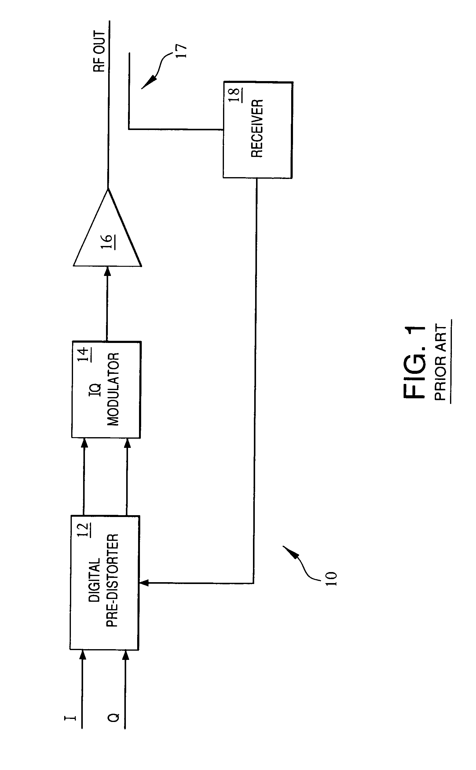
One source of spurious emissions is the base station transmitter amplifier that is used to amplify signals prior to transmission as wireless (e.g., RF) signals to wireless (e.g., mobile) units in a wireless communication network, such as a cellular voice and / or data network.

Method used


Image

  • Digital pre-distortion for the linearization of power amplifiers with asymmetrical characteristics
  • Digital pre-distortion for the linearization of power amplifiers with asymmetrical characteristics
  • Digital pre-distortion for the linearization of power amplifiers with asymmetrical characteristics

Examples


Embodiment Construction

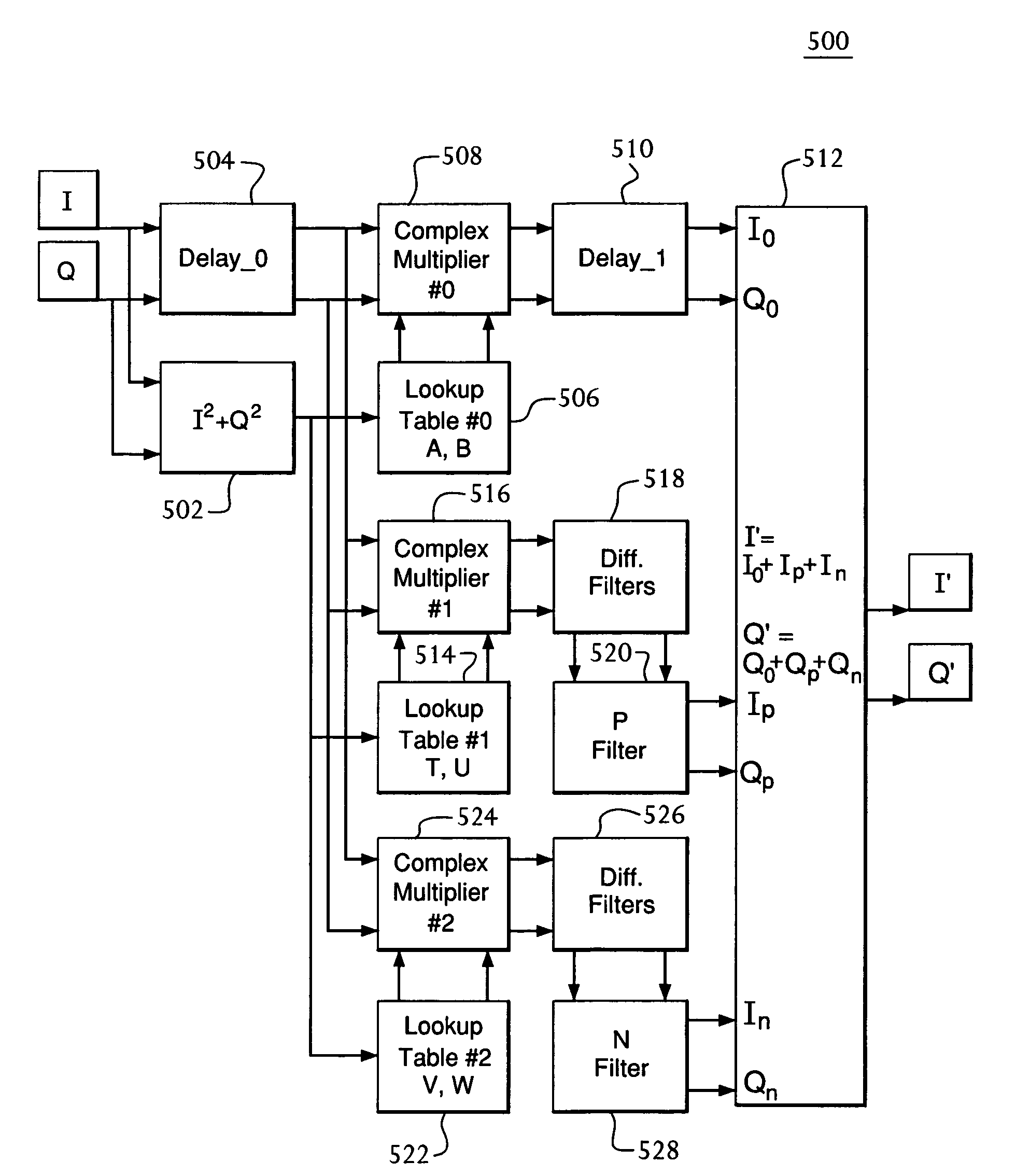
[0014]Embodiments of the present invention are directed to techniques that reduce spurious emissions in wireless communication networks to levels that satisfy current requirements. In particular, embodiments of the present invention involve the application of pre-distortion to an input signal to generate a pre-distorted signal that, when applied, e.g., to an amplifier, results in lower spurious emissions in the resulting amplified signal, where the amplifier has asymmetrical characteristics (e.g., an asymmetry between spurious emissions that occur at frequencies below the center frequency and spurious emissions that occur at frequencies above the center frequency).

Pre-Distortion Technique of the '490 Application

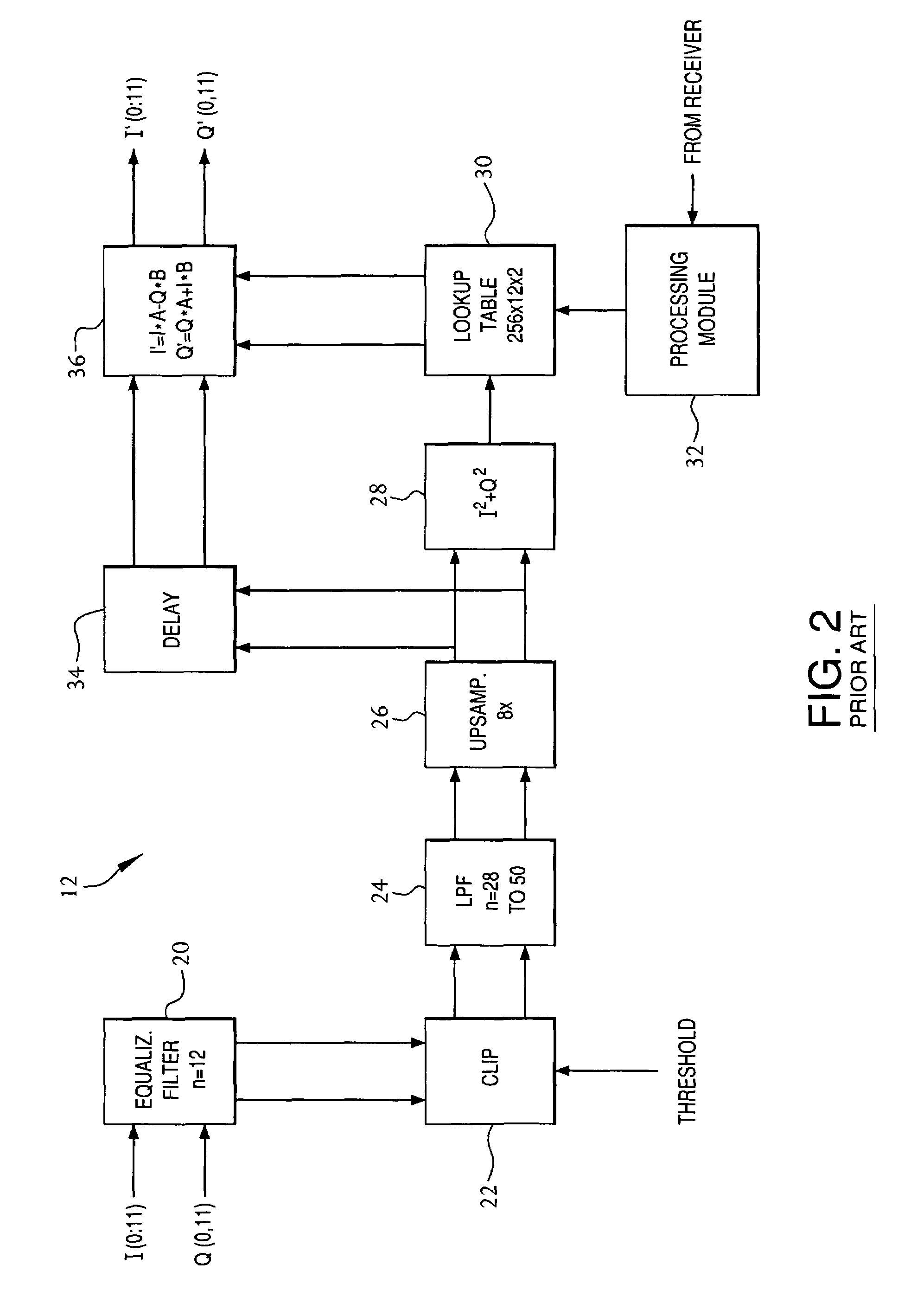
[0015]The '490 application describes a technique for reducing spurious emissions using digital pre-distortion that was sufficient to meet previously existing regulations and standards. According to the '490 application, pre-distortion, whose magnitude and phase are frequency-...


PUM


Abstract

An input signal is pre-distorted to reduce spurious emissions resulting from subsequent signal amplification. Frequency-dependent pre-distortion is preferably implemented in combination with frequency-independent pre-distortion, where the frequency-dependent pre-distortion corresponds to amplifier distortion that has a magnitude that is proportional to the frequency offset from the carrier frequency and a ±90° phase shift on either side of the carrier frequency. The frequency-dependent pre-distortion is generated by differentiating waveforms corresponding to two different sets of pre-distortion parameters with respect to time. In one embodiment, one of the differentiated waveforms is applied to a positive-frequency filter and the other to a negative-frequency filter to generate positive- and negative-frequency pre-distortion signals, respectively, to account for asymmetries in the amplifier characteristics. In another embodiment, only one of the differentiated waveforms is applied to an asymmetric filter (i.e., either a positive-frequency filter or a negative-frequency filter).

Description

CROSS-REFERENCE TO RELATED APPLICATIONS[0001]This is a continuation-in-part of co-pending application Ser. No. 10 / 607,924, filed on Jun. 27, 2003, the teachings of which are incorporated herein by reference.[0002]The subject matter of this application is also related to the subject matter of (a) U.S. patent application Ser. No. 09 / 395,490, filed on Sep. 14, 1999 (“the '490 application”), (b) U.S. patent application Ser. No. 10 / 068,343, filed on Feb. 5, 2002, (c) U.S. patent application Ser. No. 10 / 153,446, filed on May 22, 2002 (“the '446 application”), (d) U.S. patent application Ser. No. 10 / 153,289, filed on May 22, 2002 (“the '289 application”), and (e) U.S. patent application Ser. No. 10 / 217,930, filed on Aug. 13, 2002, the teachings of all five of which are incorporated herein by reference.FIELD OF THE INVENTION[0003]The present invention relates to signal processing, and, in particular, to the pre-distortion of signals for transmission, for example, in a wireless communication...

Claims


Application Information

Patent Timeline
Patent Type & Authority Patents(United States)
IPC IPC(8): H04L25/49H03F1/26H04L27/36H04B1/62H03F1/32
CPCH03F1/3294H03F1/3241H03G3/002H04B1/62H03F1/32
Inventor VELLA-COLEIRO, GEORGE P.
Owner COMMSCOPE TECH LLC
Learn More