
Linearization device for a power amplifier

a power amplifier and linearization technology, applied in the field of linearization devices of power amplifiers, can solve the problems of increasing the requirements of radio communication devices, in terms of spectral efficiency, and non-linear behavior of power amplifiers, and achieve the effects of reducing and increasing the number of power amplifiers

Inactive Publication Date: 2013-04-30
THALES SA +1
View PDF7 Cites 5 Cited by
  • Summary
  • Abstract
  • Description
  • Claims
  • Application Information

AI Technical Summary

Benefits of technology

[0013]Another advantage of the present invention is that it does not require the use of large capacity memories.
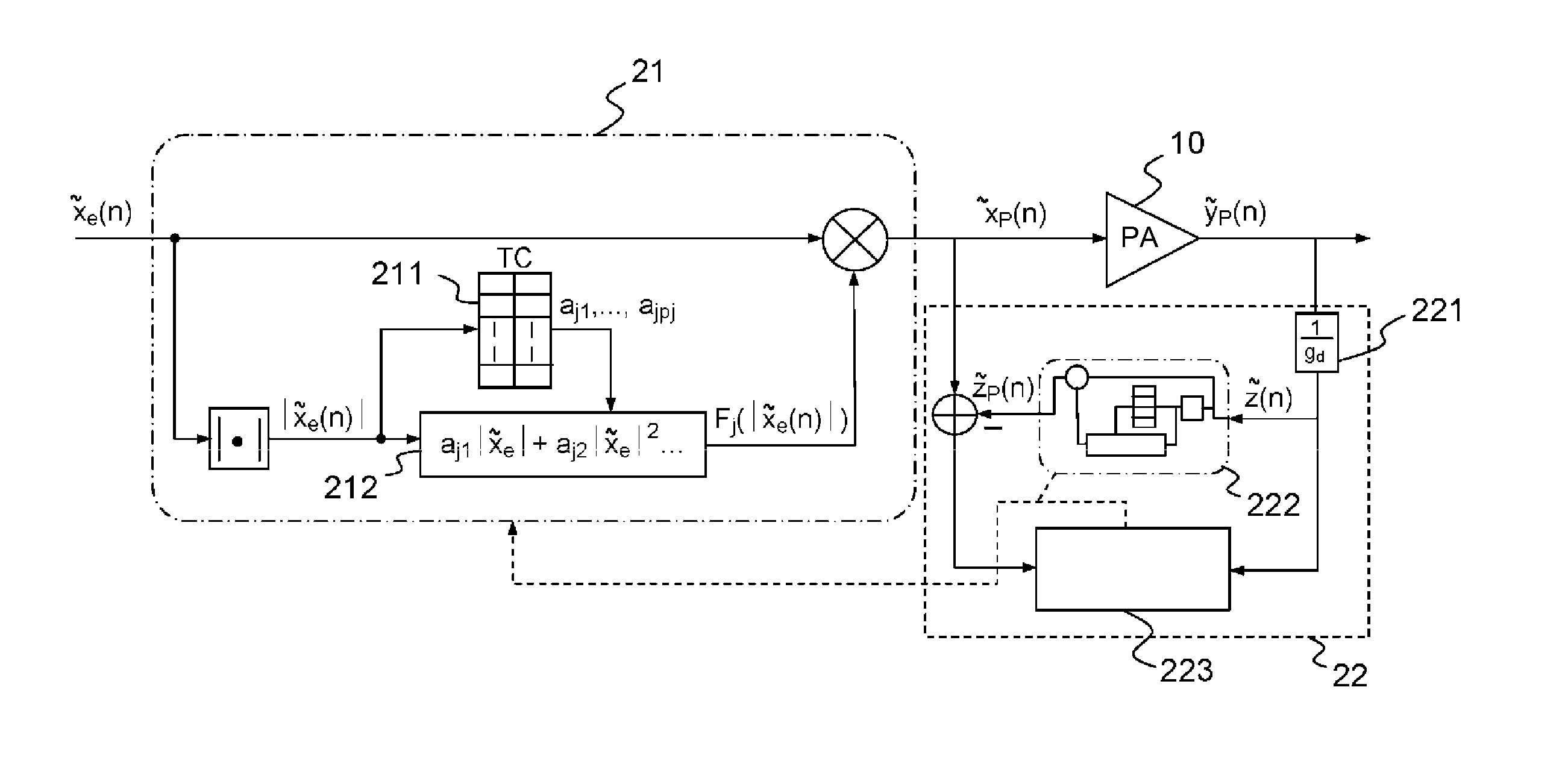
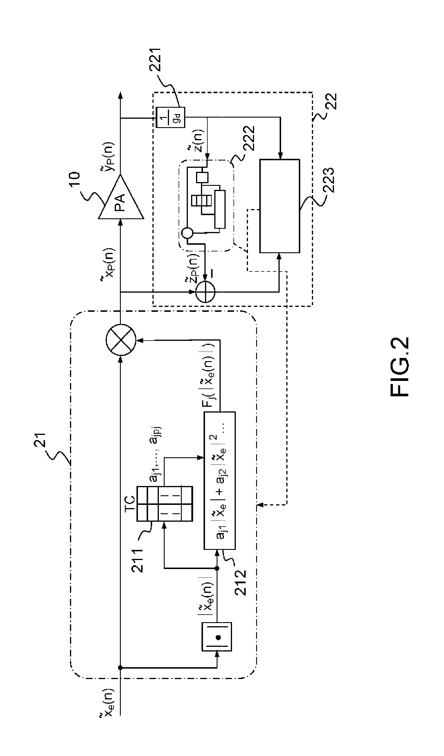
[0014]Accordingly, the invention is a linearization device for a power amplifier using adaptive digital baseband predistortion including a pre-inverse block receiving a complex discretized input signal {tilde over (x)}e(n) and restoring a complex predistorted signal {tilde over (x)}p(n) at the power amplifier input, wherein the pre-inverse block includes a first module and a second module receiving the modulus of the complex input signal |{tilde over (x)}e(n)| at the input whose value is included in an amplitude domain varying between two minimum and maximum values, the amplitude domain being split into a plurality of segments, the first module including a correspondence table associating with each value of the complex input signal modulus contained in a given segment, a predefined set of a plurality of parameters defining a parametric model implemented in the second module via a function Fj, the second module restoring a value Fj(|{tilde over (x)}e(n)|), the complex predistorted signal resulting from multiplying the complex input signal {tilde over (x)}e(n) by the value Fj(|{tilde over (x)}e(n)|).
[0015]In one embodiment of the invention, each of said predefined sets of parameters for a given segment k can define the complex coefficients of a polynomial of order Pk.
[0016]In one mode of embodiment of the invention, the minimum amplitude Amin being zero, the amplitude domain can be split into a number NTCP of segments of the same length Lseg equal to the ratio of the maximum amplitude Amax of the amplitude domain to the number of segments Amax / NTCP, the segments of the amplitude domain then being intervals [(j−1)Lseg, jLseg], the correspondence table associating for each of the intervals a set of complex parameters aj<sub2>1< / sub2>, . . . , ajP<sub2>j < / sub2>corresponding to the coefficients of order j1, jPj of the polynomial of order Pj.
[0017]In one embodiment of the invention, the identification of the pre-inverse block can be based on an indirect architecture formed by an identification block arranged in parallel with the power amplifier, the identification block identifying the sets of parameters for each segment of the amplitude domain of the complex input signal modulus |{tilde over (x)}e(n)| by minimizing the error between the input signal {tilde over (x)}p(n) and the output signal {tilde over (y)}(n) of the power amplifier in at least one iteration.
[0018]In one embodiment of the invention, the identification block can include an attenuator attenuating the output signal {tilde over (y)}(n) of the power amplifier by a gain 1 / gd equal to the inverse of the desired gain of the power amplifier, the attenuated complex signal {tilde over (z)}(n) being applied at the input of a post-inverse block restoring a signal {tilde over (z)}p(n) at the output, an estimation block determining the identification parameters of the pre-inverse block from the difference between the input signal {tilde over (x)}p(n) of the power amplifier and the output signal {tilde over (z)}p(n) of the post-inverse block by minimizing the quadratic error using the least squares technique.

Problems solved by technology

The non-linear behaviour of power amplifiers notably generates phase and amplitude distortions on the transmitted signals, which notably generate spectral feedback outside the useful signal channel.
Such spectral feedback is undesirable: first, the requirements demanded from radio communication devices, in terms of spectral efficiency, are increasingly severe, with the increasing variety of wireless communication devices.
Secondly, spectral feedback has a negative influence on the correct operation of devices situated close to the system including a power amplifier.
The correspondence table technique offers the advantage of being simple to implement; however, this technique has the drawback of the relatively long convergence time.
Furthermore, the use of large dimension tables may be required, necessitating storage memories that may be difficult to implement.
The implementation of parametric models considerably increases the complexity of the system and may cause problems of instability when the orders of polynomials employed are high, or even problems of non-convergence of algorithms.

Method used


Image

  • Linearization device for a power amplifier
  • Linearization device for a power amplifier
  • Linearization device for a power amplifier

Examples


Embodiment Construction

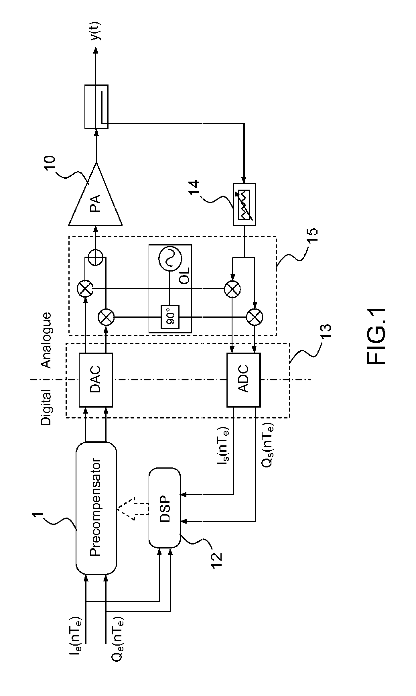
[0023]FIG. 1, shows the schematic diagram of a transmission chain including a power amplifier combined with a known adaptive digital baseband predistortion device.

[0024]A transmission chain known in itself from prior art, for transmitting a phase and amplitude modulated radio frequency signal for example, may include a power amplifier 10 restoring an amplified signal y(t). The digitized input signal may be in baseband, for example after shaping by a low-pass filter achieved by a transmission filter not shown in the figure, then broken down into in-phase and quadrature components Ie(nTe) and Qe(nTe), Te being the inverse of the signal sampling frequency. The components Ie(nTe) and Qe(nTe) are applied at the input of a precompensator 11, restoring after processing of the two input signals, two digital output signals.

[0025]In parallel, the I and Q components are applied at the input of a digital signal processing module DSP 12.

[0026]A conversion block 13 includes a digital-to-analogue ...


PUM


Abstract

A linearization device for a power amplifier using adaptive digital baseband predistortion includes a pre-inverse block receiving a complex discretized input signal {tilde over (x)}e(n) and restoring a complex predistorted signal {tilde over (x)}p(n) at the power amplifier input. The pre-inverse block includes a first module and a second module receiving the modulus of the complex input signal |{tilde over (x)}e(n)| at the input whose value is included in an amplitude domain varying between two values 0 and Amax, the amplitude domain being split into a plurality of segments, the first module associating with each value of the complex input signal modulus |{tilde over (x)}e(n)| contained in a given segment, a set of several parameters defining a model implemented in the second module via a function Fj, the second module restoring a value Fj(|{tilde over (x)}e(n)|), the complex predistorted signal resulting from multiplying the complex input signal {tilde over (x)}e (n) by the value Fj(|{tilde over (x)}e(n)|).

Description

CROSS-REFERENCE TO RELATED APPLICATION[0001]This application claims priority to foreign French patent application No. FR 0906280, filed on Dec. 23, 2009, the disclosure of which is incorporated by reference in its entirety.FIELD OF THE INVENTION[0002]The present invention relates to a linearization device for a power amplifier. It applies notably to the field of power amplifiers used in transmission chains of radio communication systems.BACKGROUND[0003]In the field of radio communications, signal transmission requires the use of power amplifiers, essential in transmission chains. The power amplifiers used in radio communications are generally non-linear; non-linearity phenomena are all the more present in that current power amplifiers operate in areas close to their saturation, with a view to optimizing their performance, input dynamics are significant, and variable envelope signals are increasingly used. The non-linear behaviour of power amplifiers notably generates phase and ampli...

Claims


Application Information

Patent Timeline
Patent Type & Authority Patents(United States)
IPC IPC(8): H03F1/26
CPCH03F1/3258H03F1/3247
Inventor PEYRESOUBES, GEORGESFEUVRIE, BRUNOABI HUSSEIN, MAZENWANG, YIDE
Owner THALES SA
Learn More