
High efficiency, remotely reconfigurable remote radio head unit system and method for wireless communications

A remote radio frequency head and wireless communication technology, applied in the field of wireless communication systems, can solve problems such as poor power efficiency

Active Publication Date: 2013-01-09
DALI SYST LTD
View PDF13 Cites 6 Cited by
  • Summary
  • Abstract
  • Description
  • Claims
  • Application Information

AI Technical Summary

Problems solved by technology

RRU performance limitations are driven in part by poor power efficiency of RF amplifiers

Method used


Image

  • High efficiency, remotely reconfigurable remote radio head unit system and method for wireless communications
  • High efficiency, remotely reconfigurable remote radio head unit system and method for wireless communications
  • High efficiency, remotely reconfigurable remote radio head unit system and method for wireless communications

Examples


Embodiment Construction

[0085] The present invention is a new RRU system using an adaptive digital pre-distortion algorithm. The present invention is a hybrid system of digital modules and analog modules. The interplay of the digital and analog blocks of the hybrid system linearizes the spectral growth and improves the power efficiency of the PA while maintaining or increasing the wide bandwidth. Thus, the present invention achieves higher efficiency and higher linearity of wideband composite modulated carriers.

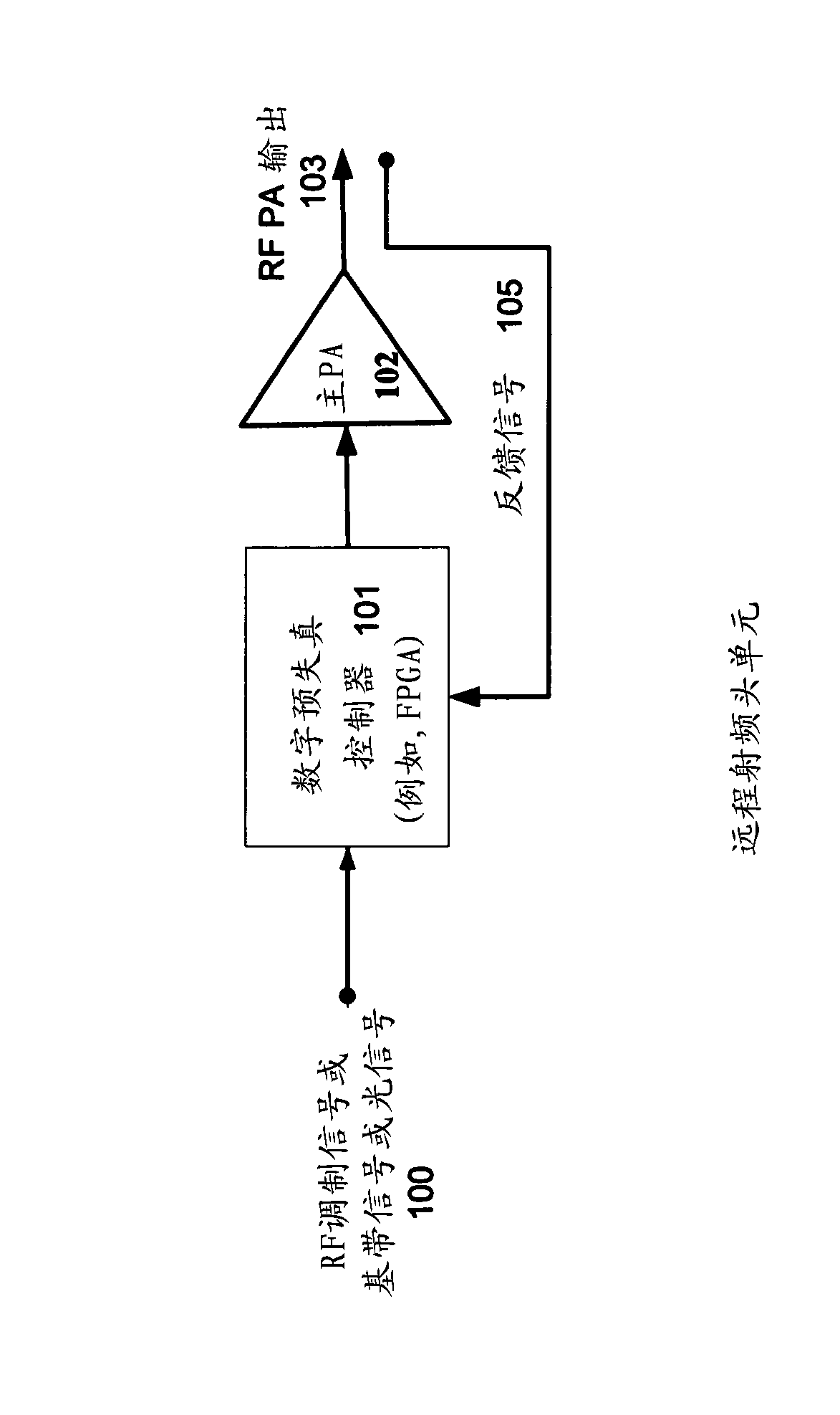
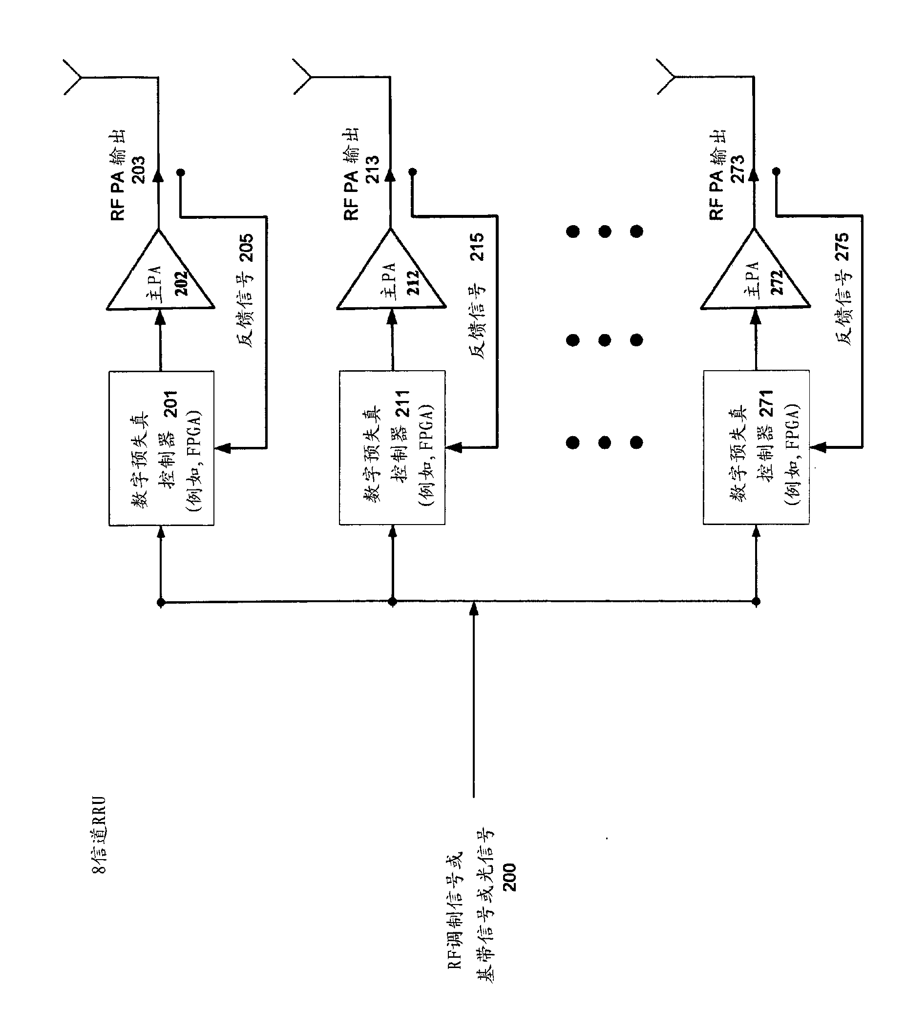
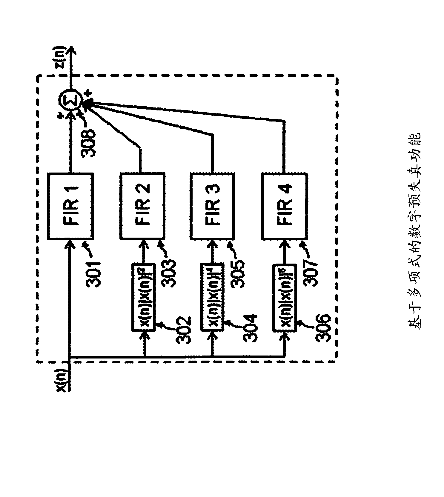
[0086] figure 1 is a high-level block diagram illustrating the basic system architecture, sometimes referred to as a remote radio head unit or RRU, which, at least for some embodiments, can be considered to include digital and analog blocks and feedback paths. The digital module is a digital predistortion controller 101 including PD algorithm, other auxiliary DSP algorithms and related digital circuits. The analog modules are the main power amplifier 102, other auxiliary analog circuits...


PUM


Abstract

A remote radio head unit (RRU) system for achieving high efficiency and high linearity in wideband communication systems is disclosed. The present invention is based on the method of adaptive digital predistortion to linearize a power amplifier inside the RRU. The power amplifier characteristics such as variation of linearity and asymmetric distortion of the amplifier output signal are monitored by a wideband feedback path and controlled by the adaptation algorithm in a digital module. Therefore, embodiments of the present invention can compensate for the nonlinearities as well as memory effects of the power amplifier systems and also improve performance, in terms of power added efficiency, adjacent channel leakage ratio and peak-to-average power ratio.; The present disclosure enables a power amplifier system to be field reconfigurable and support multi-modulation schemes (modulation agnostic), multi-carriers, multi-frequency bands and multi-channels. As a result, the remote radio head system is particularly suitable for wireless transmission systems, such as base- stations, repeaters, and indoor signal coverage systems.

Description

[0001] related application [0002] This application claims the benefit of the following applications: [0003] U.S. Patent Application No. 12 / 415,676, filed March 31, 2009, and U.S. Patent Application No. 61 / 041,164, filed March 31, 2008, as extended by application 12 / 415,676; this application Also claiming the benefit of U.S. Provisional Patent Application No. 61 / 172,642, filed April 24, 2009; [0004] U.S. Patent Application No. 12 / 603,419, filed October 21, 2009, U.S. Patent Application No. 12 / 108,507, filed April 23, 2008, as extended by application 12 / 603,419, and application 12 / 108,507 extends U.S. Patent Application No. 60 / 925,577, filed April 23, 2007; [0005] U.S. Patent Application No. 12 / 330,451, filed December 8, 2008, and U.S. Patent Application No. 61 / 012,416, filed December 7, 2007, as extended by application 12 / 330,451; [0006] U.S. Patent Application Serial No. 11 / 961,969, filed December 20, 2007, U.S. Patent Application Serial No. 60 / 877,035, filed Decem...

Claims


Application Information

Patent Timeline
IPC IPC(8): H04W88/08H03F1/26H03F1/30H03F3/20H03F3/68
CPCY02B60/50Y02D30/70H04L25/20H04L25/49H04L27/0008H03F1/304H03F1/3241
Inventor 肖恩·帕特里克·斯特普尔顿金万容肖英曹敬俊
Owner DALI SYST LTD
Learn More