Simulation testing of digital logic circuit designs

a technology of digital logic and circuit design, applied in the field of circuit design methodology, can solve the problems that the current simulation model cannot be relied on to emulate asynchronous logic behavior, the problem is complicated, and the current simulation model cannot model circuits with synchronous and asynchronous data paths correctly

Inactive Publication Date: 2007-07-31
GLOBALFOUNDRIES INC
View PDF5 Cites 30 Cited by
  • Summary
  • Abstract
  • Description
  • Claims
  • Application Information

AI Technical Summary

Problems solved by technology

Simply adding delay to current simulation models cannot be relied on to emulate asynchronous logic behavior because, for example, the delays cannot account for such effects as temperature or voltage shifts.
The problem is further complicated when the digital logic circuit includes both synchronous and asynchronous data paths.
Current simulation models do not model circuits with both synchronous and asynchronous data paths correctly.

Method used


Image

  • Simulation testing of digital logic circuit designs
  • Simulation testing of digital logic circuit designs
  • Simulation testing of digital logic circuit designs

Examples


Embodiment Construction

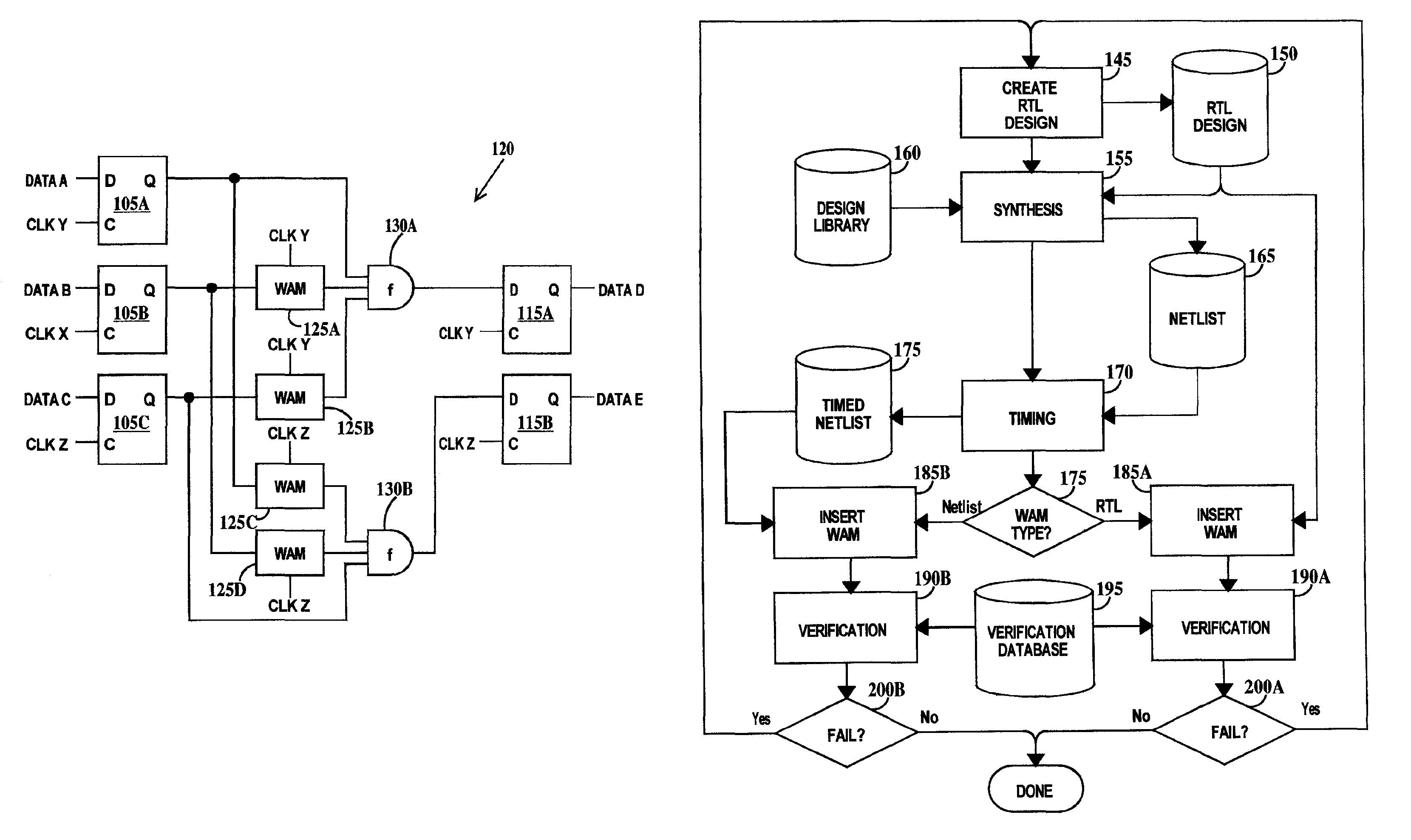
[0019]It should be understood that the present invention is applied to circuit designs and not physical circuits and that testing of the designs is accomplished by building simulation models of the circuit and applying simulated input to the simulation model of the circuit.

[0020]For the purposes of the present invention the terms testing and verification should be considered as synonymous terms.

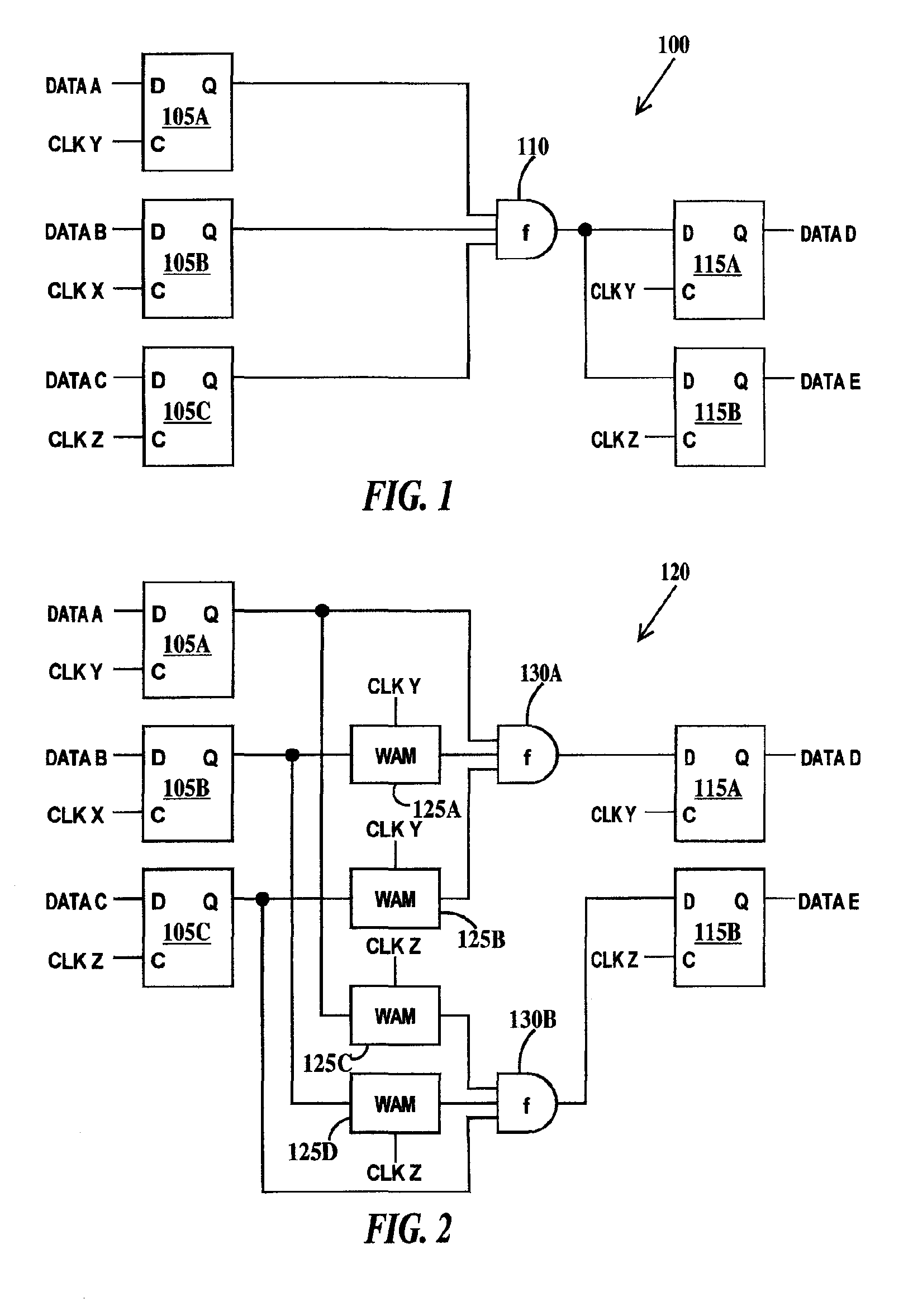
[0021]A clock cycle is defined as the time between consecutive rising or consecutive falling edges of the clock signal. An asynchronous data path is defined as a signal path between an output of a source latch responsive to a first clock signal and the input of a destination latch responsive to a second clock signal where the first and second clock signals are not supplied from the same clock pin (i.e. are from different clock domains and the rising and falling edges of the two clock signals are not constrained to occur at the same time). A synchronous data path is defined as a signal path be...


PUM


Abstract

A method and system for testing a circuit design. The method including generating a simulation model of the circuit design, the circuit design comprising one or more source latches, one or more destination latches and a logic function connected between the source latches and the destination latches; generating a modified simulation model of the simulation model by inserting random skew between an output of each source latch and an input of the logic function only in asynchronous data paths between the source latches and the destination latches of the simulation model; and running the modified simulation model.

Description

FIELD OF THE INVENTION[0001]The present invention relates to the field of circuit design methodology; more specifically, it relates to a method for simulation testing of circuit designs having asynchronous data paths.BACKGROUND OF THE INVENTION[0002]Simulation of digital logic circuits is performed is using simulation models. The logic function of logic designs containing asynchronous logic boundaries wherein a signal is launched by a circuit element in a first clock domain and captured by a circuit element in a second clock domain, the first and second clock domains specified to be asynchronous to each other, can not be verified by current simulation models. Simply adding delay to current simulation models cannot be relied on to emulate asynchronous logic behavior because, for example, the delays cannot account for such effects as temperature or voltage shifts. Current simulation models also ignore the possibility of transition glitches between the sending of logic pulses. The prob...

Claims


Application Information

Patent Timeline
Patent Type & Authority Patents(United States)
IPC IPC(8): G06F17/50
CPCG06F17/5031G06F30/3312
Inventor BLANCO, RAFAELGRANATO, SUZANNEKAMPF, FRANCIS A.MASSEY, DOUGLAS T.
Owner GLOBALFOUNDRIES INC
Why Eureka
Try Eureka