Frame mount latch assembly for subsurface aircraft servicing pit

Inactive Publication Date: 2007-08-07
CAVOTEC ACQUISITION US
View PDF22 Cites 5 Cited by
  • Summary
  • Abstract
  • Description
  • Claims
  • Application Information

AI Technical Summary

Benefits of technology

[0014]The present invention provides a system for fastening a pit lid mounting frame to the peripheral seat of the subsurface pit which eliminates the requirement for hold down bolts that are exposed to the elements. According to the system of the present invention the pit lid mounting frame is provided with an annular frame mount latch ring that is secured in a horizontal orientation depending beneath the undersurface of the pit lid mounting frame by bolts that are spaced periodically throughout the circumference of the frame mount latch ring. Since these bolts are located beneath the pit lid mounting frame and within the enclosure of the pit, they are protected from the elements.
[0017]The pit lid frame may easily be removed by overcoming the downwardly biasing force on the hooks provided by the internal springs within the frame mount latches. Removal is achieved by overcoming the bias of the spring end lifting the outer telescoping tubular portion of the frame mount latch relative to an inner portion located concentrically therewithin so as to lift the hooks high enough to clear the frame mount latch rings. The hooks are thereupon twisted about the axis of the tubular body portion so as to be redirected radially inwardly to provide clearance relative to the frame mount latch ring. The springs are then released. The pit lid frame, together with the frame mount latch ring can then be lifted from the pit lid mounting frame seat at the upper extremity of the fiberglass pit.
[0019]The frame mount latch assembly of the invention provides a system that permits faster replacement of a pit lid mounting frame for a subsurface aircraft servicing pit. Moreover, because the latch system is located entirely within the enclosure of the pit, it is not exposed to the elements and thereby deteriorates less rapidly. Moreover, even if the latches do become broken, their broken parts cannot result in foreign objects and debris that can be sucked into an aircraft engine, because they are located entirely within the confines of the pit.

Problems solved by technology

One difficulty with this pit lid mounting frame attachment system is that the hold down bolts can bind up due to exposure to the elements.
Once they are removed for any reason they are quite difficult to reinstall.
This is because debris can collect in the internally tapped bolt holes.
If these bolts are not properly reinstalled or otherwise secured they can become loose on the runway.
Runway debris and other foreign objects on an aircraft loading apron can be sucked into the jet engines of an aircraft and create serious damage.

Method used


Image

  • Frame mount latch assembly for subsurface aircraft servicing pit
  • Frame mount latch assembly for subsurface aircraft servicing pit
  • Frame mount latch assembly for subsurface aircraft servicing pit

Examples


Embodiment Construction

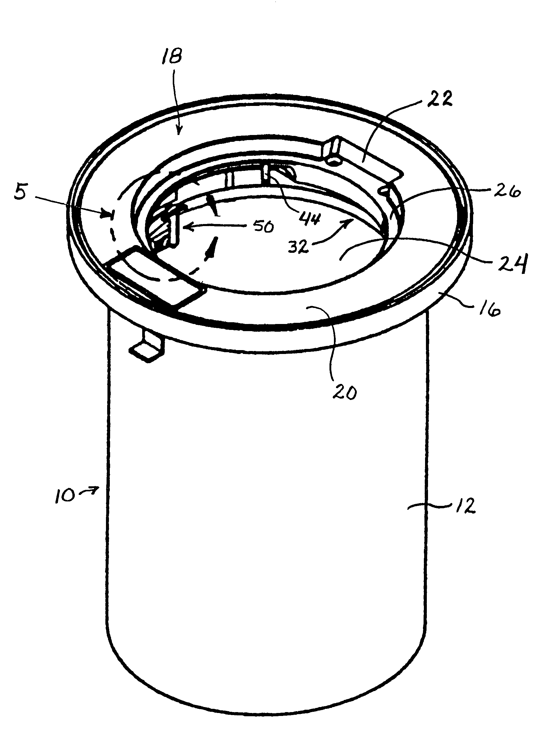
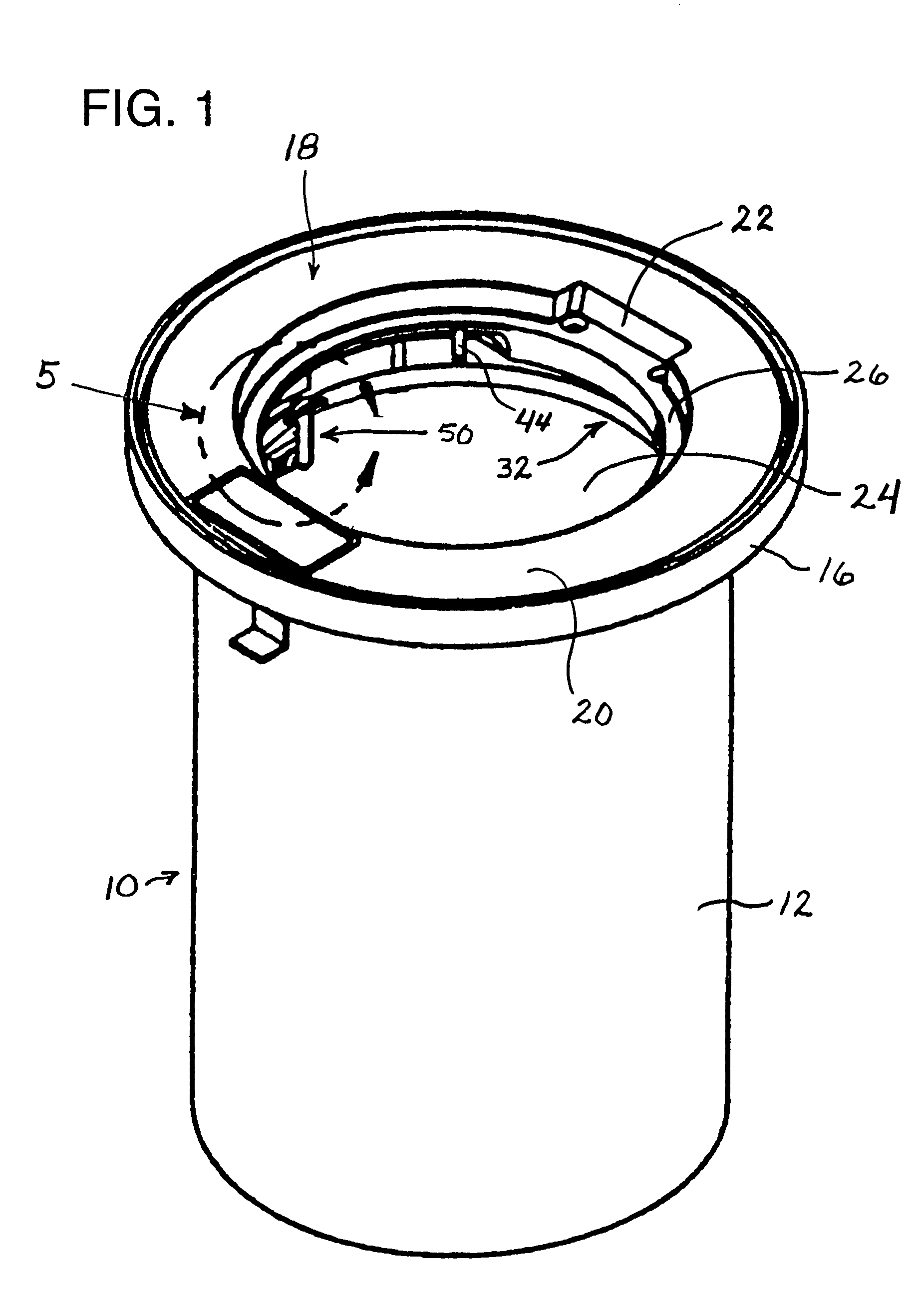
[0041]FIG. 1 illustrates a prefabricated, subsurface fiberglass aircraft servicing pit indicated generally at 10. The particular prefabricated aircraft servicing pit 10 illustrated has a cylindrical, annular configuration, although aircraft servicing pits of this type often have a generally rectilinear shape as well. The aircraft servicing pit 10 is designed to be buried beneath a surface across which aircraft travel when not airborne, such as a tarmac docking apron.

[0042]The aircraft servicing pit 10 has a laterally surrounding, cylindrical, annular upright side wall 12 which forms a laterally surrounding, upright enclosing structure. In aircraft servicing pits having a rectilinear shape there are four upright side walls which meet at slightly rounded right angle corners.

[0043]The upright cylindrical wall 12 of the aircraft servicing pit 10 is topped with a laterally outwardly projecting bearing ledge 14, the peripheral edge extremity of which is turned upwardly to form a surroundi...


PUM


Abstract

A subsurface aircraft servicing pit is provided with a hold down assembly that secures a pit lid mounting frame in position on a bearing seat at the top of a prefabricated pit enclosure. A frame mount latch ring is suspended in spaced relation beneath the underside of the pit lid mounting frame and inwardly from the walls of the pit enclosure. At least a pair of frame mount latches are provided on opposite sides of the pit. The latches have bases secured to the pit walls and hooks that extend over the top of the frame mount latch ring. The frame mount latches are constructed so as to exert a downward force on the frame mount latch ring, thus holding the peripheral margin of the pit lid mounting frame tightly against a peripheral bearing seat surrounding the pit opening. The necessary force exerted by the frame mount latches may be provided by a coil spring located within the structure of each frame mount latch.

Description

BACKGROUND OF THE INVENTION[0001]1. Field of the Invention[0002]The present invention relates to a latching or fastening mechanism for securing a pit lid mounting frame to a subsurface chamber for servicing aircraft.[0003]2. Description of the Prior Art[0004]At modern aircraft terminals the servicing of aircraft on the ground is often performed using subsurface pits, which frequently are prefabricated structures. Such aircraft servicing pits are installed at aircraft docking, fueling, and loading areas beneath the surface of the tarmac across which aircraft travel during docking and departure maneuvers. The pits forming subsurface chambers are typically constructed of fiberglass, steel, concrete, or aluminum. These pits are quite often constructed as complete enclosures with surrounding walls, a floor, and an access lid at the top seated within a frame disposed upon the bearing flange at the top of the prefabricated pit. When the lid is closed it lies substantially flush with the su...

Claims


Application Information

Patent Timeline
IPC IPC(8): E02D29/14
CPCE02D29/14E02D29/1427
Inventor PETERSEN, CRAIGJOHNSON, EYNON S.
Owner CAVOTEC ACQUISITION US
Why Eureka
Try Eureka