Semiconductor based air conditioning device

a technology of thermoelectric cooling chip and air conditioning device, which is applied in the direction of domestic cooling apparatus, lighting and heating apparatus, heating types, etc., can solve the problems of consuming a lot of energy, heavy and bulky compressor, and inconvenient installation and transportation, so as to achieve less energy, facilitate installation and transportation, and produce coldness

Active Publication Date: 2007-08-07
CHEN CHUAN SHENG
View PDF4 Cites 18 Cited by
  • Summary
  • Abstract
  • Description
  • Claims
  • Application Information

AI Technical Summary

Benefits of technology

[0005]The primary purpose of the present invention is to provide a novel air conditioning device to replace the traditional air conditioners and refrigerators, which not only consumes less energy but also is environmentally friendly. The present invention mainly utilizes a specialized semiconductor chip, thermoelectric cooling chip, for producing the coldness. A cooling circulating member and a heat dissipating member are configured at the two sides of the thermoelectric cooling chip. The coldness produced by the thermoelectric cooling chip is delivered by a cold conduction plate and cooling pipes, and is stored in fins of the cooling circulating member. A temperature controller determines a desired temperature and the coldness stored by the fins are blown out as cool air by a fan. Similarly, the heat produced by the chip is dissipated by the heat dissipating member. As such, the present invention could reach the desired temperature within a short period of time without the conventional compressor. The present invention therefore is easier to install and transport, consumes less power, and produces almost no noise and pollution to the environment.

Problems solved by technology

The compressor is heavy and bulky, making the installation and transportation very inconvenient.
The compressor also consumes a lot of energy, in addition to the annoying noise it produces.
On the other hand, the refrigerant is also not environmentally friendly.

Method used


Image

  • Semiconductor based air conditioning device
  • Semiconductor based air conditioning device
  • Semiconductor based air conditioning device

Examples


Embodiment Construction

[0011]The following descriptions are of exemplary embodiments only, and are not intended to limit the scope, applicability or configuration of the invention in any way. Rather, the following description provides a convenient illustration for implementing exemplary embodiments of the invention. Various changes to the described embodiments may be made in the function and arrangement of the elements described without departing from the scope of the invention as set forth in the appended claims.

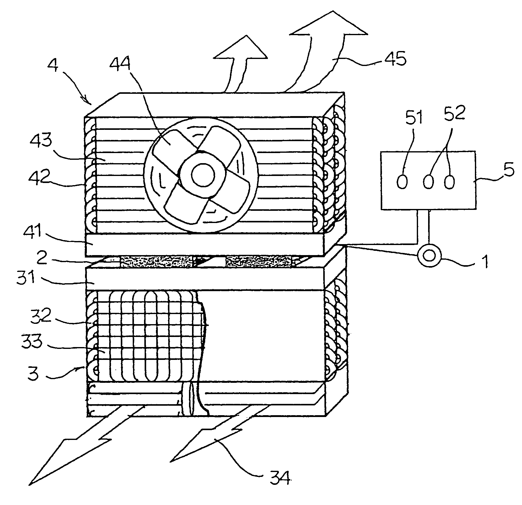
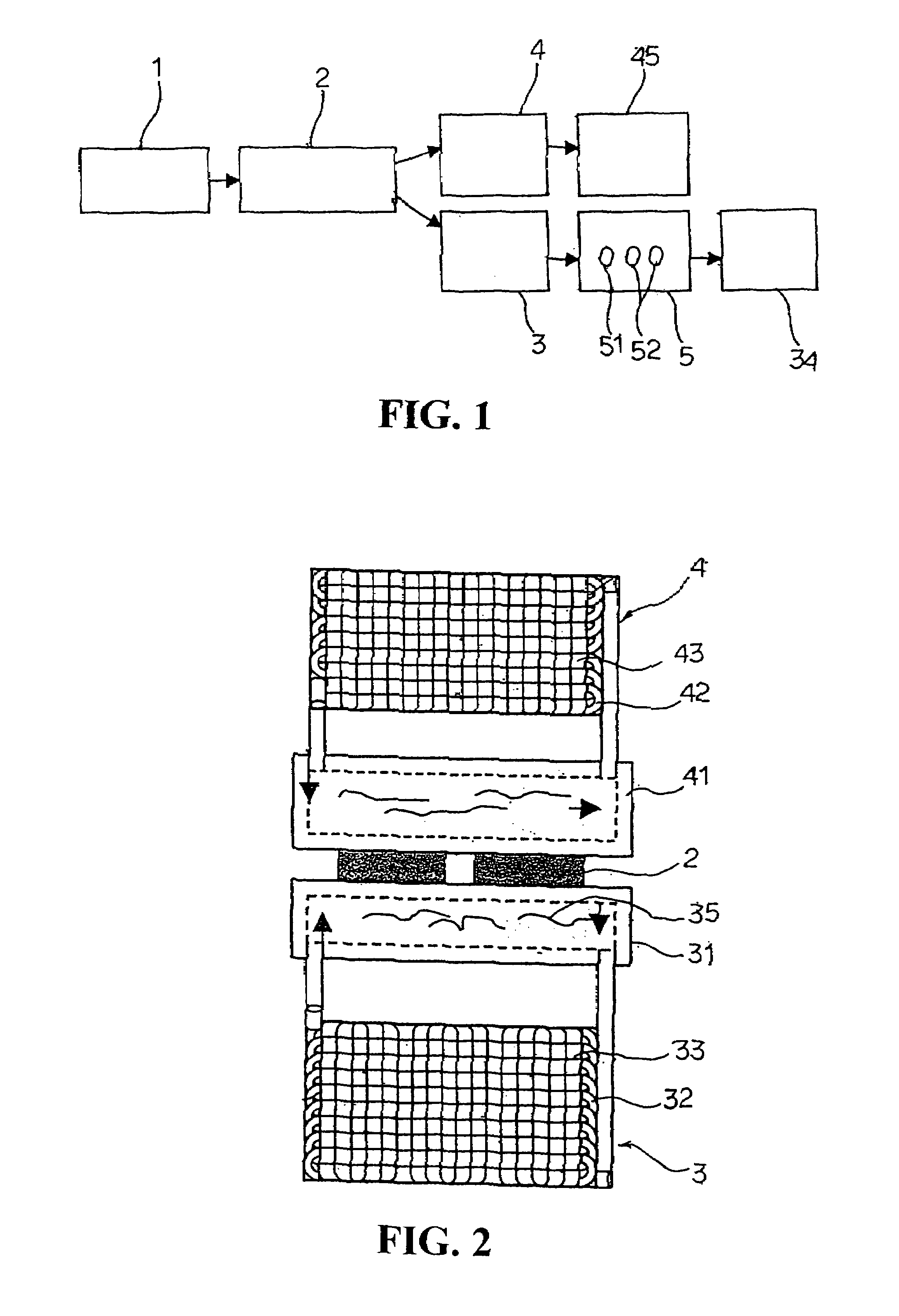
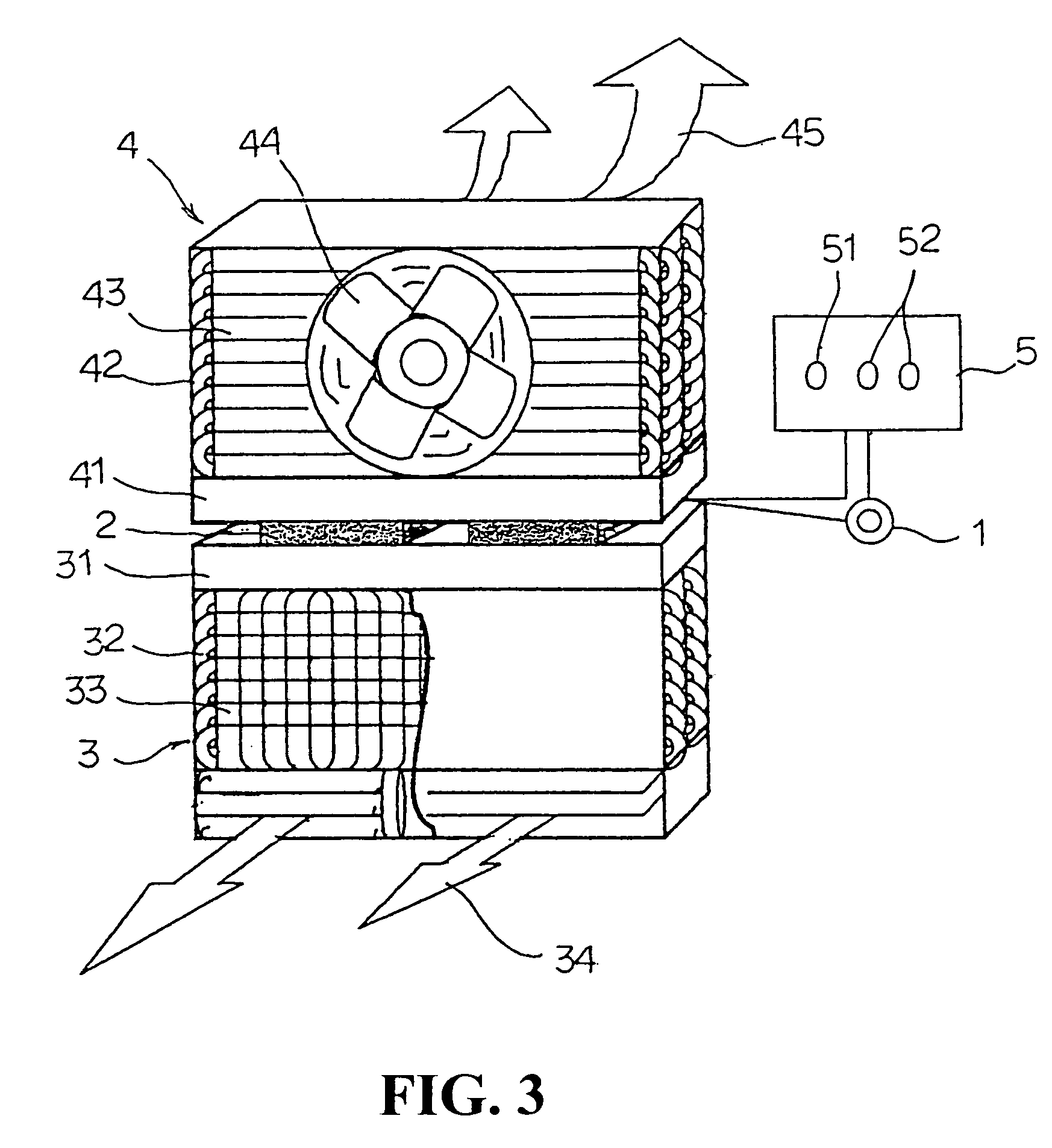
[0012]As shown in FIGS. 1˜3, the present invention mainly contains a power supply member 1, at least a thermoelectric cooling chip 2, a cooling circulating member 3, a heat dissipating member 4, and a temperature controller 5. The cooling circulating member 3 and the heat dissipating member 4 are fixedly installed on a cold production surface and a heat production surface of the thermoelectric cooling chip 2, respectively. The cooling circulating member 3 contains a cold conduction plate 31, cool...


PUM


Abstract

The present invention mainly utilizes a specialized semiconductor ship, the so-called thermoelectric cooling chip, for producing the coldness. A cooling circulating member and a heat dissipating member are configured at the two sides of the thermoelectric cooling chip. The coldness produced by the thermoelectric cooling chip is delivered by a cold conduction plate and cooling pipes, and is stored in fins of the cooling circulating member. A temperature controller determines a desired temperature and the coldness stored in the fins are blown out as cool air by a fan. Similarly, the heat produced by the chip is dissipated by the heat dissipating member. As such, the present invention could reach the desired temperature within a short period of time without the conventional compressor. The present invention therefore is easier to install and transport, consumes less power, and produces almost no noise and pollution to the environment.

Description

BACKGROUND OF THE INVENTION[0001](a) Technical Field of the Invention[0002]The present invention generally relates to air conditioning devices and, more particularly, to an air conditioning device utilizing a thermoelectric cooling chip.[0003](b) Description of the Prior Art[0004]Traditional air conditioners and refrigerators utilize compressor and refrigerant to produce the required low temperatures. The use of the compressor has quite a few disadvantages. The compressor is heavy and bulky, making the installation and transportation very inconvenient. The compressor also consumes a lot of energy, in addition to the annoying noise it produces. On the other hand, the refrigerant is also not environmentally friendly.SUMMARY OF THE INVENTION[0005]The primary purpose of the present invention is to provide a novel air conditioning device to replace the traditional air conditioners and refrigerators, which not only consumes less energy but also is environmentally friendly. The present inv...

Claims


Application Information

Patent Timeline
Patent Type & Authority Patents(United States)
IPC IPC(8): F25B21/02F02B37/18
CPCF24F5/0042F25B21/02F25B2321/021F25B2321/0251Y02T10/12
Inventor CHEN, CHUAN-SHENG
Owner CHEN CHUAN SHENG
Why Eureka
Try Eureka