Injection molding system

Inactive Publication Date: 2006-06-15
LU HSIAO TING
View PDF4 Cites 10 Cited by
  • Summary
  • Abstract
  • Description
  • Claims
  • Application Information

AI Technical Summary

Benefits of technology

[0011] An objective of the present invention is to prov

Problems solved by technology

Injection molding machines are widely used in modem industries and consume considerable electricity.
However, since the conditions for injection molding are set by the operator, the speed of the motor 4′ is low when at a small flow operation.
The speed of the motor 4′ becomes low, which would cause overheating of the motor 4′ after a long-term operation, leading to damage to the motor 4′.
Thus, the low-speed operation of the motor 4′ by the client is so arbitrary that damage to the motor 4′ occurs easily.
In a case that the operator increases the frequency

Method used


Image

  • Injection molding system
  • Injection molding system
  • Injection molding system

Examples


Example

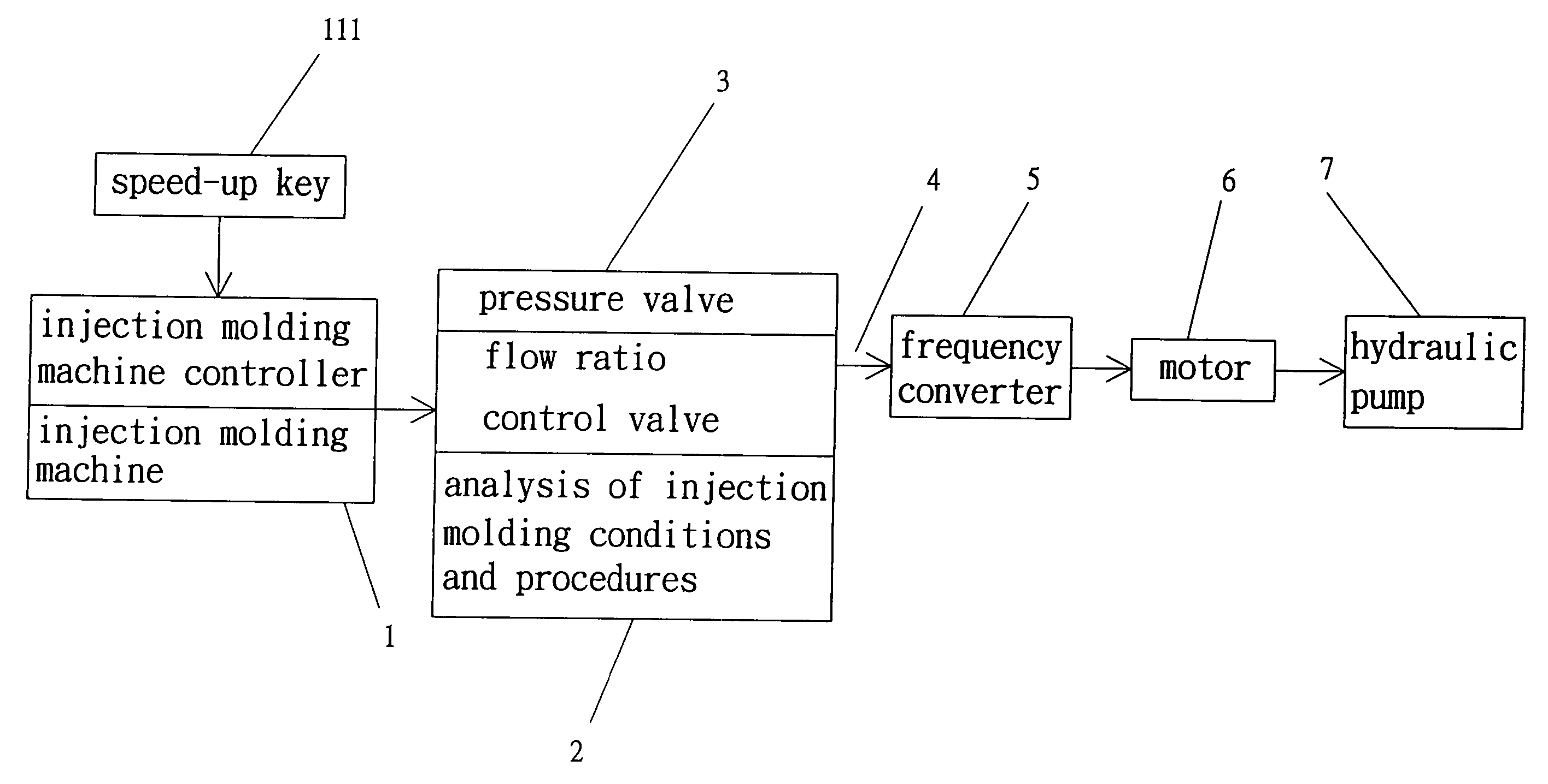
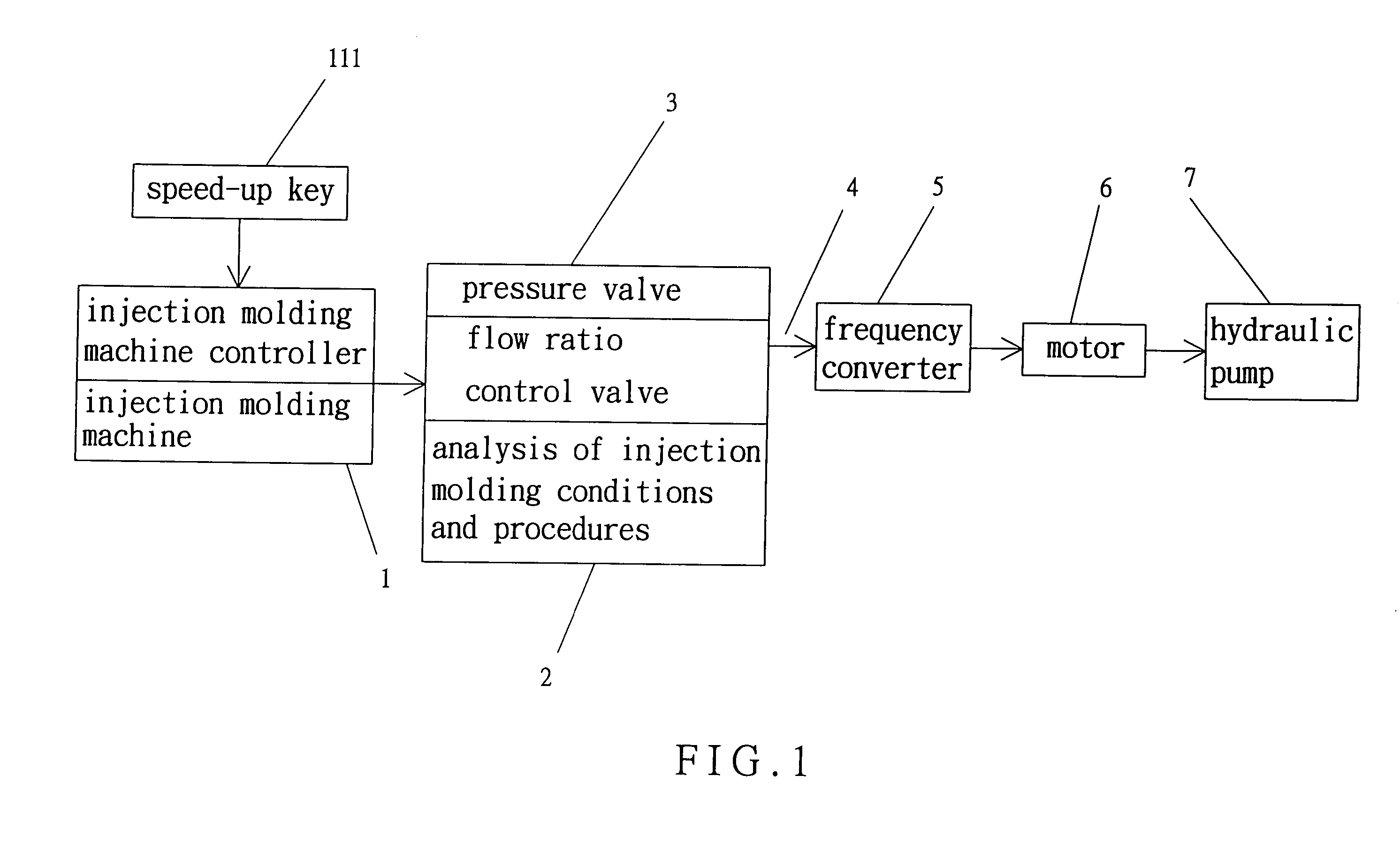
[0028] Referring to FIG. 1, an injection molding system in accordance with the present invention comprises an injection molding machine 1, an injection molding machine controller 11, a pressure valve 3, a flow ratio control valve 4, means for analyzing injection molding conditions and procedures 2, a frequency converter 5, a motor 6, and a hydraulic pump 7. The injection molding machine controller 11 operates in response to different injection molding conditions and procedures and controls operation of the pressure valve 3, the flow ratio control valve 4. The injection molding machine controller 11 further controls operation of the injection molding machine 1 and the frequency converter 5 that is connected to the motor 6 and the hydraulic pump 7.

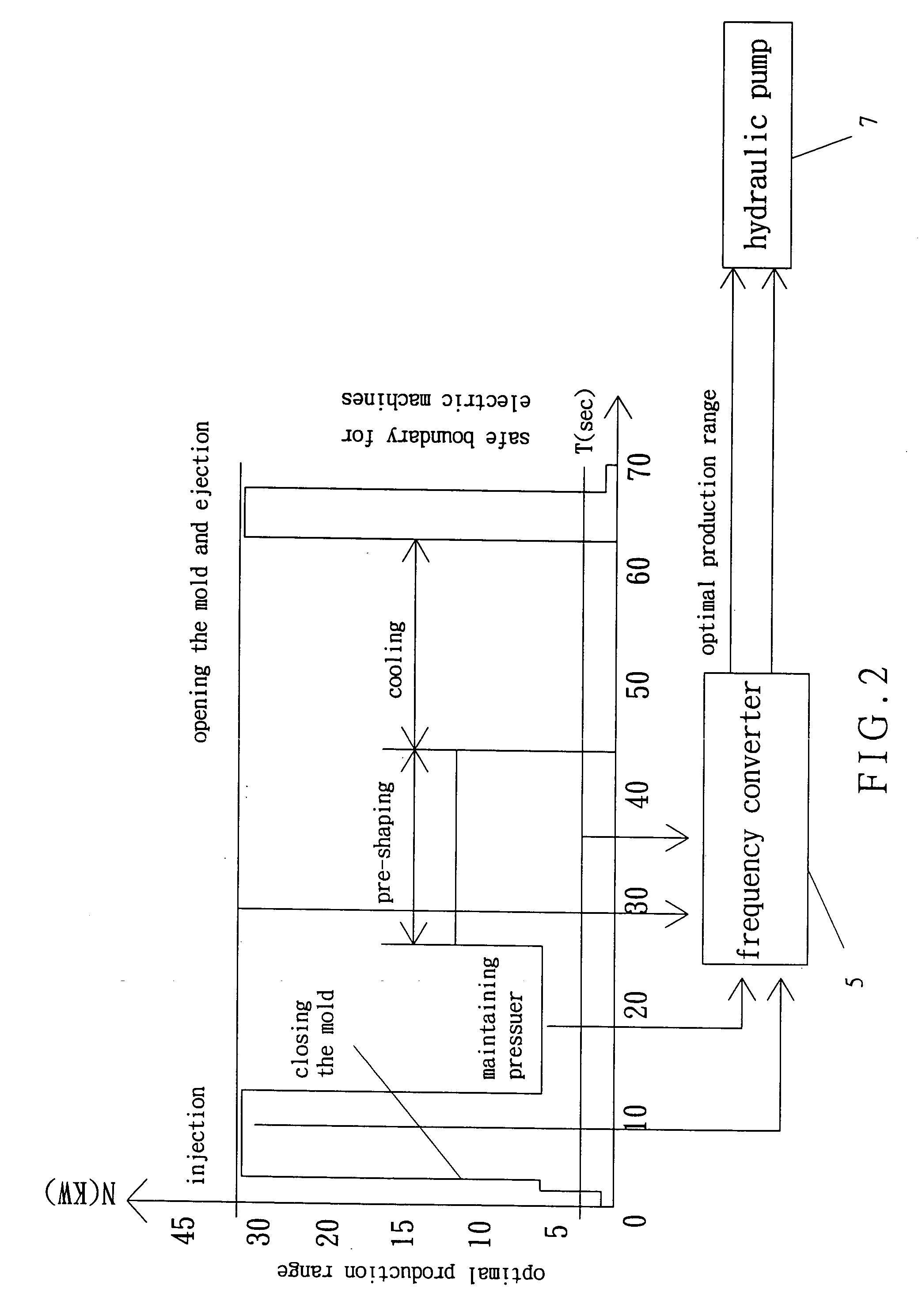
[0029] Referring to FIGS. 1 and 2, injection molding machines 1 of different types are listed and classified to analyze different conditions of injection molding, such as closing the mold (multiple stages), feeding the injection molding sea...


PUM

PropertyMeasurementUnit
Pressureaaaaaaaaaa
Frequencyaaaaaaaaaa

Abstract

An injection molding system includes an injection molding machine, a pressure valve, a flow ratio control valve, a frequency converter, and the flow ratio control valve, a motor controlled by the frequency converter, a hydraulic pump connected to the motor, and an injection molding machine controller for controlling the injection molding machine and the frequency converter. Injection molding conditions and procedures for controlling operation of the pressure valve and the flow ratio control valve are analyzed. The injection molding machine controller sets a maximum output frequency for the frequency converter and a maximum flow for the hydraulic pump, preventing inappropriate operation of a user and avoiding waste of energy. The injection molding machine controller further sets a maximum speed and a minimum speed of the motor and sets a maximum speed and a minimum speed of the hydraulic pump.

Description

BACKGROUND OF THE INVENTION [0001] 1. Field of the Invention [0002] The present invention relates to an injection molding system. In particular, the present invention relates to an injection molding system with a frequency converter. [0003] 2. Description of the Related Art [0004] Injection molding machines are widely used in modem industries and consume considerable electricity. The expenditure in electricity is about 30% of the overall cost of production. Different procedures require different amounts of energy, wherein the energy consumed by some procedures may be ten or more times of that by other procedures. It is therefore the most important issue to the manufacturers to reduce the energy consumption. FIG. 4 of the drawings illustrates a conventional injection molding system using a frequency converter. The injection molding system comprises an injection molding machine 1′, an injection molding machine controller 11′, a pressure valve 3′, a frequency converter 2′, a frequency ...

Claims


Application Information

Patent Timeline
IPC IPC(8): B29C45/77
CPCB29C45/82B29C2945/76498B29C2945/76501B29C2945/76528B29C2945/76545B29C2945/76595B29C2945/76605B29C2945/76785
Inventor LU, HSIAO TING
Owner LU HSIAO TING
Why Eureka
Try Eureka