Internal combustion engine with air-fuel mixture injection

a technology of air-fuel mixture and combustion engine, which is applied in the direction of combustion engine, fuel injection apparatus, charge feed system, etc., can solve the problems of waste of time, reduce the loss of driving force at a high-revving compressor, and reduce the length of piping

Inactive Publication Date: 2007-08-07
ORBITAL ENGINE CO PTY LTD
View PDF5 Cites 3 Cited by
  • Summary
  • Abstract
  • Description
  • Claims
  • Application Information

AI Technical Summary

Benefits of technology

[0012]According to the first aspect of the present invention, air-fuel mixture injection valve device for injecting mixture of fuel and air to an internal combustion engine, and the compressor driven by a power from a crankshaft for supplying compressed air to the injection valve device, characterized in that one end of the compressor on the air inlet side is connected to the air-intake pipe in the internal combustion engine, loss of driving force at a high revolution of the compressor is reduced with a simple structure by using the inlet negative pressure of the air-intake pipe.
[0013]According to the second aspect of the present invention, since one end on the air inlet side is connected to an air-intake pipe from the upstream of a throttle valve to a case of the air cleaner, the length of piping can be reduced and the size of the entire apparatus can be reduced.
[0014]According to a first aspect of the present invention, since the air cleaner includes a venturi member formed in the case on the downstream side of a filter element thereof, and one end of the inlet channel on the side of the air-inlet port is connected to the venturi member, flow of the excessive air into the compressor is restrained by increasing the difference of inlet negative pressure by the pressure reducing effect of the venturi member to further reduce the loss of driving force, and the noise of the air-intake pulsation generated from the air-inlet port of the inlet channel can be reduced by the air cleaner case.

Problems solved by technology

The work required to compress the air discharged as excessive air, which is a useless work in a sense, is performed by the compressor.

Method used


Image

  • Internal combustion engine with air-fuel mixture injection
  • Internal combustion engine with air-fuel mixture injection
  • Internal combustion engine with air-fuel mixture injection

Examples


second embodiment

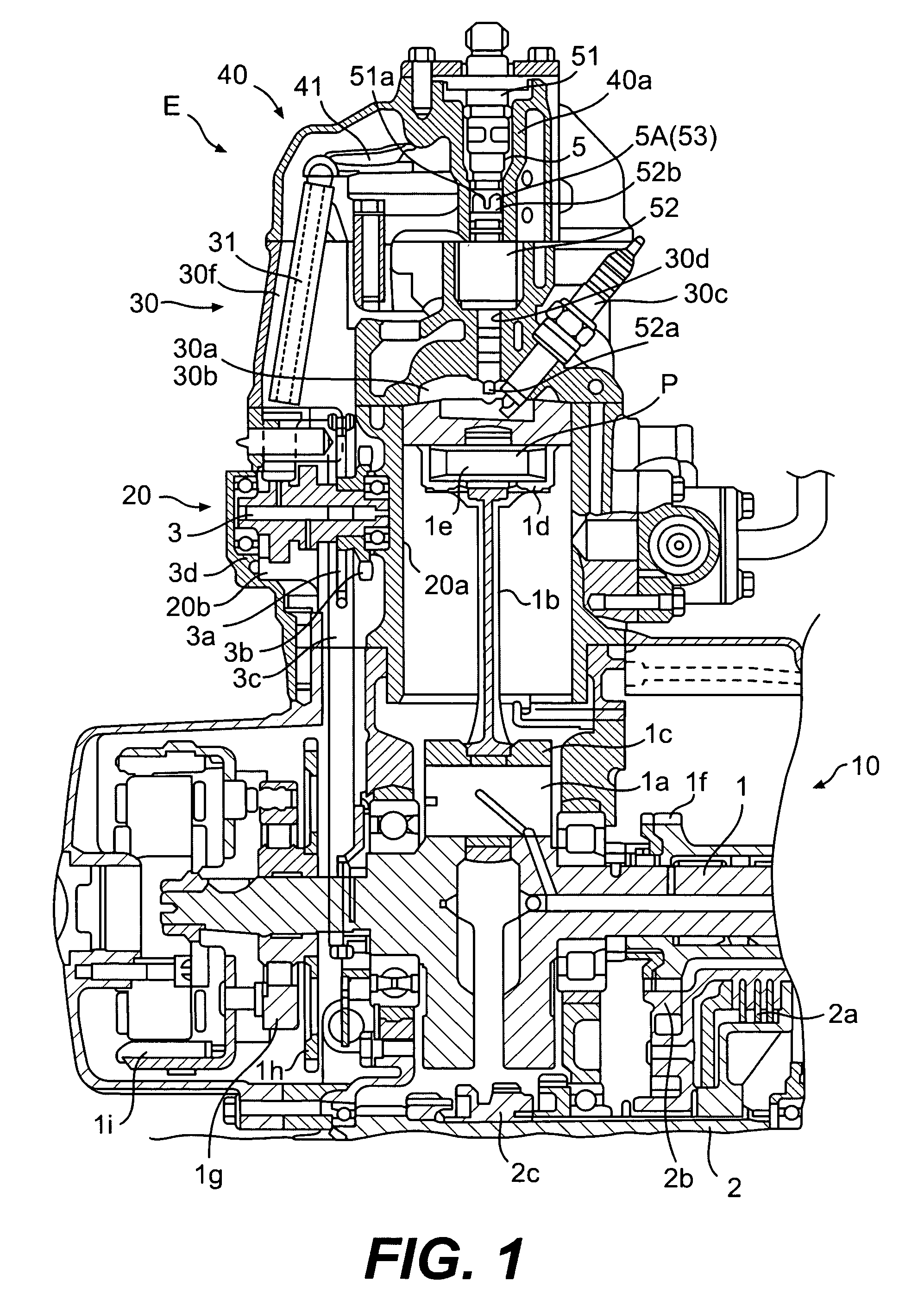
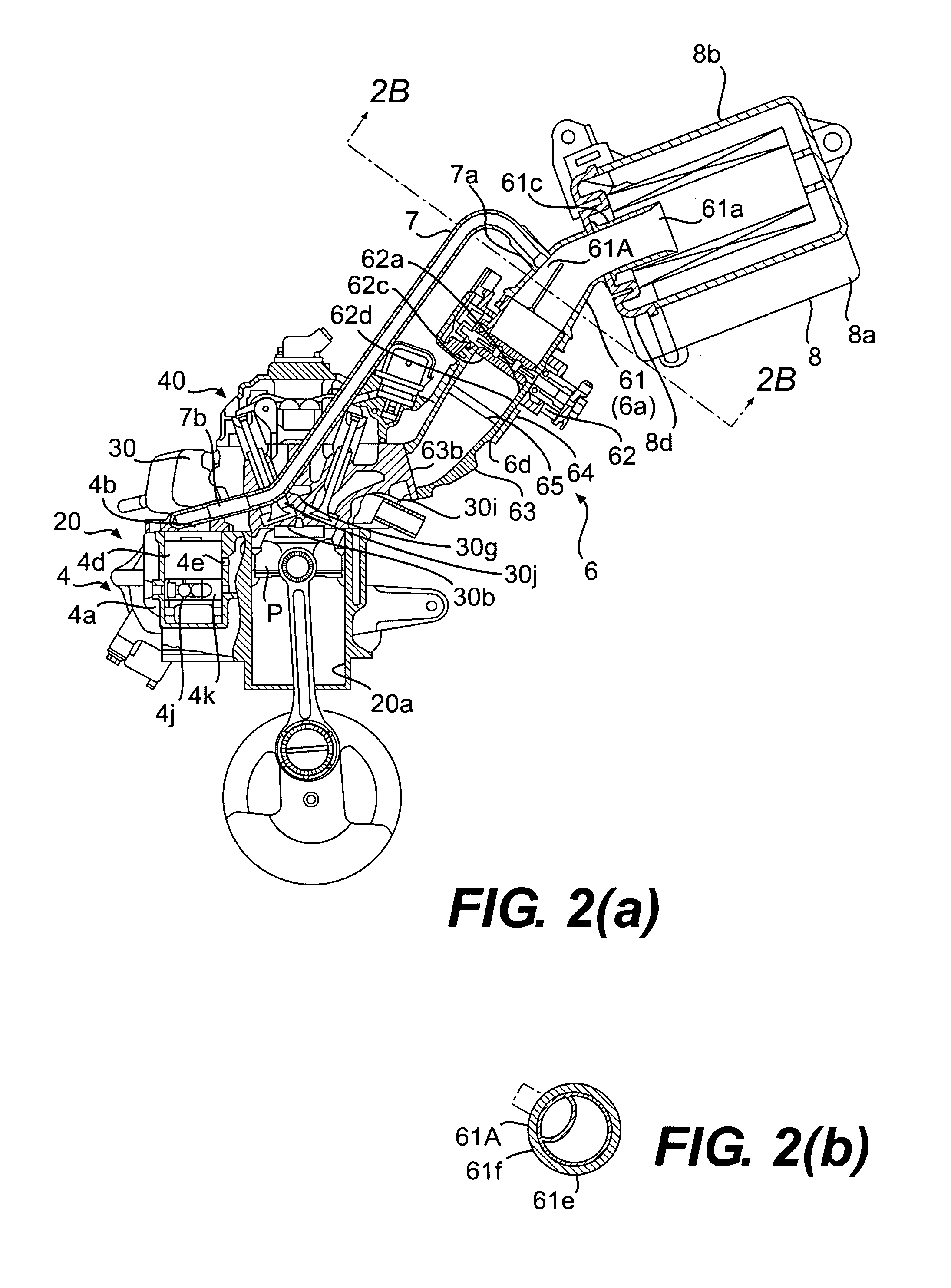
[0059]In the present invention, the aforementioned technical view is taken into account, and the inlet channel 7 has the characteristic structure for connecting the inlet port 4b of the compressor 4 and the air-intake pipe 6 of the internal combustion engine E for communicating therebetween, which is an advantageous technical selection for improving the problem.

[0060]As shown in FIGS. 2 and 3, connection of the inlet channel 7 to the air-intake pipe 6 is achieved on the upstream side of the venturi member 61A in the first connecting pipe 61 of the air-intake pipe 6, and this connection, which has been described above, is achieved by utilizing the cylindrical projection 61g on the outer periphery of the first connecting pipe 61 which corresponds to the upstream of the venturi member 61A, and by insertion of the end 7a of the inlet channel 7 on the side of the air-inlet port into the cylindrical projection 61g.

[0061]Therefore, as will be understood from the connecting structure by th...

first embodiment

[0070]In the present invention, with the above-described structure, the following effects and advantages are achieved.

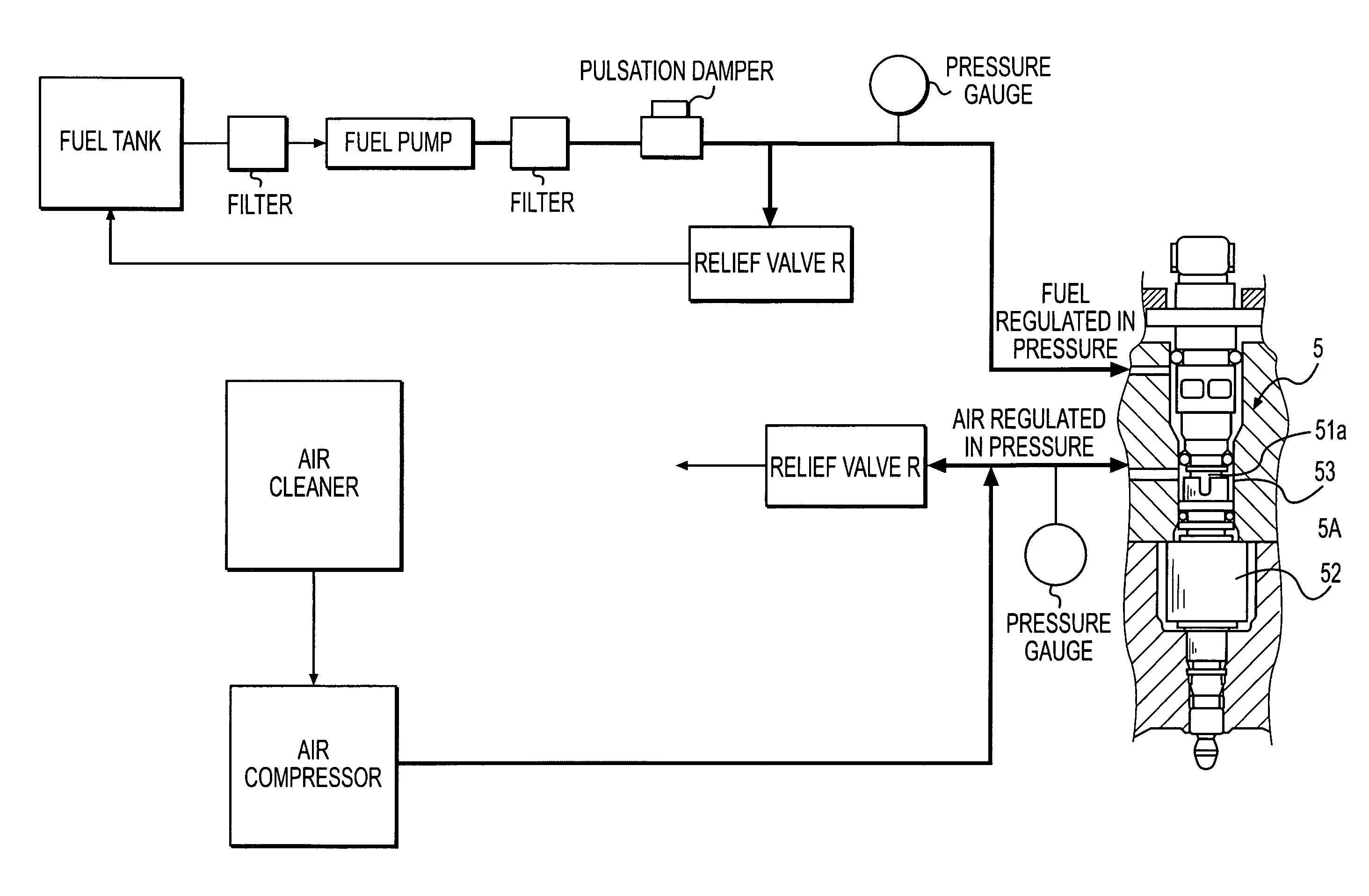
[0071]In this first embodiment, the amount of intake air to the inlet port 4b of the compressor 4 is controlled and limited by the use of intake negative pressure of the venturi member 61A in the air-intake pipe 6, useless compression of the excessive air by the compressor 4 is eliminated, and hence loss of drive force of the compressor 4 can be reduced and reduction of fuel consumption in operation of the engine E is achieved. Since the amount of intake air is controlled and limited by utilizing intake negative pressure in the air-intake pipe 6, a device which can achieve desired effects is obtained by a simple modification of the structure at a low cost.

[0072]Since the relief valves R are provided on the high-pressure air supply channels 30e, 40b for supplying the high-pressure air discharged from the discharge port 4c of the compressor 4 to the injection valve dev...


PUM


Abstract

A structure for supplying assist air to an air-fuel mixture injection valve including a device for limiting the intake air taken by a compressor, whereby a drive force of the compressor required for compressing air is reduced, and fuel efficiency is achieved. The structure includes an inlet port of the compressor and a venturi member of an air-intake pipe brought into communication via an inlet channel. The air in the air-intake pipe is regulated by the venturi member through the inlet channel by driving the compressor and is taken to the compressor. Air compressed in the compressor is supplied through a high-pressure air channel to the air introduction portion of the fuel injection valve device, where fuel injected from the fuel injection valve and high-pressure air supplied to the air introduction portion are mixed to air-fuel mixture, and the air-fuel mixture is injected by the air-fuel mixture injection valve.

Description

CROSS-REFERENCE TO RELATED APPLICATION[0001]The present application claims priority under 35 U.S.C. §119 to Japanese Patent Application No. 2004-279886 filed Sep. 27, 2004, the entire contents of which are hereby incorporated by reference.BACKGROUND OF THE INVENTION[0002]1. Field of the Invention[0003]The present invention relates to an improved technology of an internal combustion engine with air-fuel mixture injection.[0004]2. Description of Background Art[0005]An air-fuel mixture injection type 2-cycle internal combustion engine in which compressed fuel from a fuel pump and pressurized air from an air-compressor to be supplied to a fuel injection valve are regulated in pressure by a differential pressure regulator, and excessive exhaust air which is run off by the differential pressure regulator when regulating the pressure is discharged into an air cleaner is known (for example, see Japanese Patent No. 2938992 (P.2-3, FIG. 1)). In addition, an air-fuel mixture injection type 2-c...

Claims


Application Information

Patent Timeline
Patent Type & Authority Patents(United States)
IPC IPC(8): F02M67/02
CPCF02M23/062F02M23/001F02M23/003Y02T10/146Y02T10/12
Inventor CHO, MASAKI
Owner ORBITAL ENGINE CO PTY LTD
Why Eureka
Try Eureka