Cooler system for vehicle

a technology of exhaust gas recirculation and cooler, which is applied in the direction of lubrication temperature control, mechanical equipment, machines/engines, etc., can solve the problems of increasing the discharge pressure of the oil pump, increasing the oil pressure, and increasing so as to reduce the time needed to warm up the oil greatly, the differential pressure of the cooling water can be minimized, and the effect of preventing the loss of pressure of the water pump

Active Publication Date: 2016-05-31
HYUNDAI MOTOR CO LTD
View PDF24 Cites 0 Cited by
  • Summary
  • Abstract
  • Description
  • Claims
  • Application Information

AI Technical Summary

Benefits of technology

[0016]Various aspects of the present invention are directed to provide a cooler system for a vehicle which features in that cooling water and oil selectively exchange heat with EGR gas heat depending on the driving or warming up state of an engine, and in particular the time needed to warm up an oil is greatly reduced with the aid of a heat exchange operation using cooling water heated by the heat from the engine at the time of a cold start, so the lubrication conditions in the driving system can be maintained in the optimized state. Since the differential pressure of the cooling water can be minimized with the aid of the heat exchange with the EGR gas at the time of the cold start, the pressure loss of the water pump can be prevented.
[0028]In the various embodiments of present invention, the cooling water and the oil are heat-exchanged with the EGR gas depending on the driving state of the engine, and in particular the oil involves in the heat exchange operation with the EGR gas at the time of the cold start, so the time needed to reach the warm up is greatly reduced, and the well optimized state can be obtained in the driving system since there are not any problems in the friction force transfer which used to occur due to a high kinematic viscosity when the oil is a low temperature.
[0029]In addition, the present invention features in that since the lubrication state can be maintained in the optimized state in the driving system even at the time of the cold start, the wear resistance is enhanced, the fatigue strength is increased, and the durability is greatly enhanced. In particular, since the lubrication state of the engine quickly reaches the optimized state, the noises and vibrations are reduced dramatically.
[0030]Since the cooling water and the oil exchange heat with the EGR gas depending on the driving state of the engine, the differential pressure can be minimized by way of the EGR cooler at the time of the cold start, so the loss of the driving force of the water pump and the total heat of the oil cooler and the EGR cooler can be improved significantly. The fouling phenomenon of the ER cooler can be improved significantly as well.

Problems solved by technology

Such a system takes long time to increase the oil temperature during a cold operation, causing a discharge pressure of an oil pump to increase.
As an example, the increase of the discharge pressure of the oil pump results in an increase of the oil pressure, and the increase of the oil pressures results in an increase of a jointing pressure in the engine friction system, so the friction force of the engine driving system is lowered.
In particular, the low temperature oil has a high kinematic viscosity and a high oil pressure, thereby lowering the wear resistances of the engine elements and generating noises.
As a result, the durability of the engine might be greatly lowered.
Since the cooling water line has a layout passing through the EGR cooler all the time, any disadvantages occurring in an independent cooler system formed of an oil cooler and an EGR cooler cannot be overcome.
Also, since it takes long time to increase oil temperature during a cold operation, the discharge pressure of an oil pump increases, and the oil pressure increases due to the increase of the discharge pressure of the oil pump.
Further, the low temperature oil has a high kinematic viscosity and a high oil pressure, thereby lowering the wear resistances of the engine elements and generating noises.
As a result, the durability of the engine might be greatly worsened.

Method used


Image

  • Cooler system for vehicle
  • Cooler system for vehicle
  • Cooler system for vehicle

Examples


Embodiment Construction

[0038]Reference will now be made in detail to various embodiments of the present invention(s), examples of which are illustrated in the accompanying drawings and described below. While the invention(s) will be described in conjunction with exemplary embodiments, it will be understood that present description is not intended to limit the invention(s) to those exemplary embodiments. On the contrary, the invention(s) is / are intended to cover not only the exemplary embodiments, but also various alternatives, modifications, equivalents and other embodiments, which may be included within the spirit and scope of the invention as defined by the appended claims.

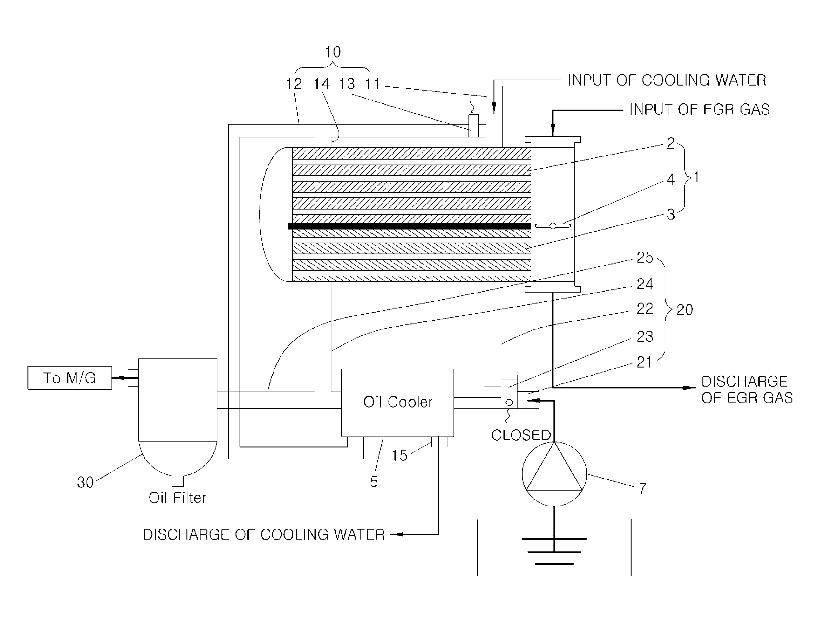
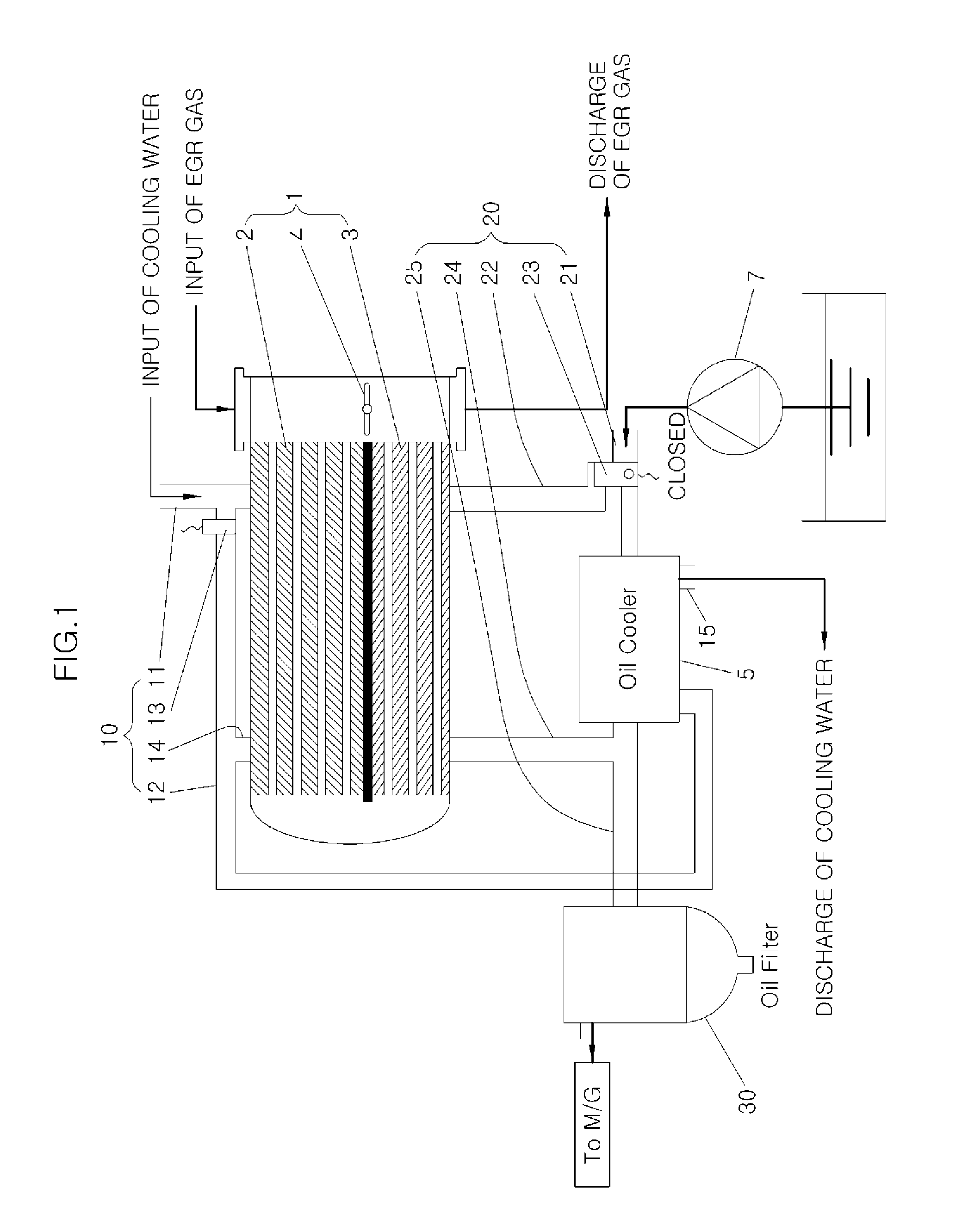
[0039]FIG. 1 is a view illustrating an exemplary integrated cooler system for a vehicle according to various embodiments of the present invention. As shown therein, the cooler system includes an EGR cooler 1 in which an EGR gas flows, the EGR gas lowering the temperature as it transfers heat to cooling water and oil, an oil cooler 5 i...


PUM


Abstract

An integrated cooler system for a vehicle includes an Exhaust Gas Recirculation cooler, an oiler cooler, a cooling water line configured to selectively transfer the cooling water directly to the oil cooler without through the EGR cooler or to the oil cooler by way of the EGR cooler depending on the warm up state of the engine, and an oil line configured to selectively transfer the oil supplied from an oil pump to the oil cooler without passing through the EGR cooler or to an oil filter after passing through the EGR cooler depending on the warm up state of the engine, the oil filter serving to filter impurities contained in the oil from the oil cooler.

Description

CROSS-REFERENCE(S) TO RELATED APPLICATIONS[0001]The present application claims priority of Korean Patent Application Number 10-2012-0087685, filed on Aug. 10, 2012, the entire contents of which application is incorporated herein for all purposes by this reference.BACKGROUND OF INVENTION[0002]1. Field of Invention[0003]The present invention relates to an oil cooler and an EGR (Exhaust Gas Recirculation) cooler for a vehicle, and particularly to an integrated cooler system for a vehicle which makes it possible to greatly reduce the time needed to reach the warm up of oil by facilitating the oil to have a heat exchange with the EGR gas at the time of a cold start, while ensuring that a driving force loss of a water pump can be reduced in such a way to minimize the differential pressure of cooling water of an EGR cooler circuit.[0004]2. Description of Related Art[0005]The EGR gas, which generally uses an exhaust gas, should be carefully handled to minimize generation of NOx due to a hig...

Claims


Application Information

Patent Timeline
Patent Type & Authority Patents(United States)
IPC IPC(8): F01M5/00F02B47/08F01P3/20
CPCF02M26/25F01M5/00F01P3/20F02B47/08F02M26/28F02M26/33F01P2060/04F01P2060/16Y02T10/121Y02T10/12
Inventor HAN, JUNGJAE
Owner HYUNDAI MOTOR CO LTD
Why Eureka
Try Eureka