Work vehicle and method for controlling work vehicle

a technology for working vehicles and work vehicles, applied in the direction of process and machine control, interengaging clutches, instruments, etc., can solve the problems of insufficient cooling of rotating parts, suppress the loss of driving force in the braking device, and reduce the incidence of overheating. , the effect of high cooling capacity

Inactive Publication Date: 2013-07-09
KOMATSU LTD
View PDF20 Cites 0 Cited by
  • Summary
  • Abstract
  • Description
  • Claims
  • Application Information

AI Technical Summary

Benefits of technology

[0006]However, in a braking device, there may be instances where the temperature of the rotating member has not decreased sufficiently when the braking device is switched from a braking state to a non-braking state. In such an instance, if the amount of supplied lubricant is switched according to the braking device being switched between braking and non-braking states as described above, there is a possibility of the amount of supplied lubricant being reduced even in a state in which the temperature of the rotating member is high, and the rotating member overheating. In order to prevent such overheating, the amount of supplied lubricant must be set high; in such an instance, the effect of minimizing the loss of driving force is reduced.
[0007]An object of the present invention is to provide a work vehicle and a method for controlling the work vehicle enabling a braking device to have minimal loss of driving force, to experience a minimal number of instances of overheating.

Problems solved by technology

However, in a braking device, there may be instances where the temperature of the rotating member has not decreased sufficiently when the braking device is switched from a braking state to a non-braking state.

Method used


Image

  • Work vehicle and method for controlling work vehicle
  • Work vehicle and method for controlling work vehicle
  • Work vehicle and method for controlling work vehicle

Examples


first embodiment

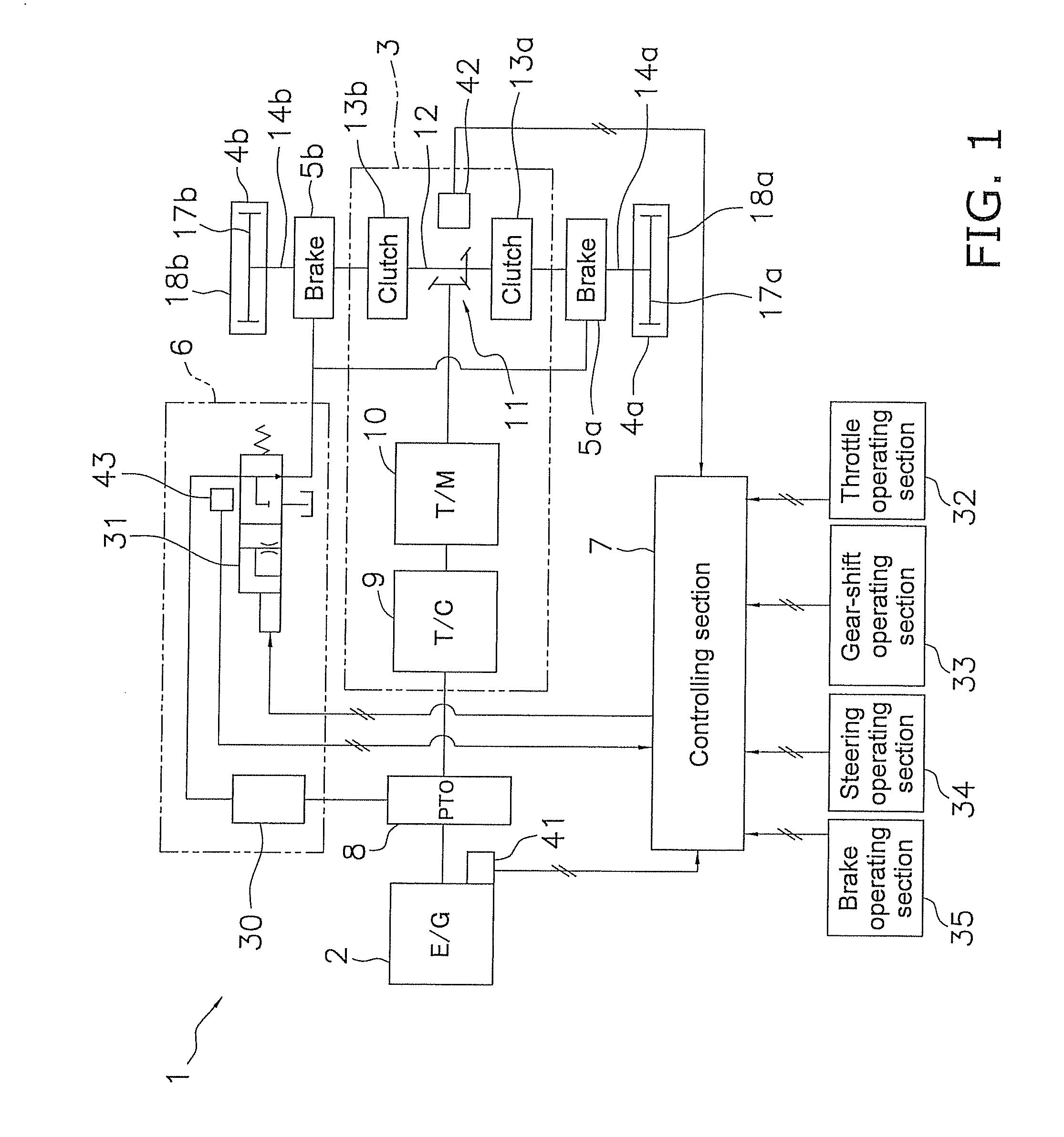
[0032]FIG. 1 is a schematic system diagram of a work vehicle 1 according to a first embodiment of the present invention. The work vehicle 1 is, for example, a bulldozer, and comprises an engine 2; a power transmission mechanism 3; a pair of traveling devices 4a, 4b; a pair of braking devices 5a, 5b; a lubricant feeding section 6; a variety of operating sections 32 through 35; a variety of sensors 41 through 43; a controlling section 7; and other components.

Engine 2

[0033]The engine 2 is a diesel engine, the output of which is controlled by adjusting the amount of fuel injected from the fuel injection pump (not shown). Specifically, the engine speed and the amount of fuel injected are adjusted according to load so that the actual engine speed matches the engine speed set by the controlling section 7. A driving force from the engine 2 is distributed via a power takeoff device 8 to the power transmission mechanism 3 and a hydraulic pump 30 described below.

Power Transmission Mechanism 3

[...

second embodiment

[0087]In the aforementioned embodiment, a decision is made in the sixth step S6 as to whether the brake disc temperature tr(n) is smaller than a predetermined target temperature α; however, a lubricant feed time required for the brake disc temperature to decrease to a predetermined target temperature as a result of the lubricant being fed at the first feed amount may be calculated, and the amount of supplied lubricant reduced from the first feed amount to the second feed amount when the lubricant feed time has elapsed from a point in time when the braking device 5a, 5b is switched from a braking state to a non-braking state. For example, in FIG. 4, a time period corresponding to a period T13 is calculated as the lubricant feed time, and the amount of supplied lubricant is reduced from the first feed amount Q1 to the second feed amount Q2 when the lubricant feed time (T13) has elapsed from the point in time when a period T12 ends (shown by P1 in FIG. 4). In such an instance, the lubr...

third embodiment

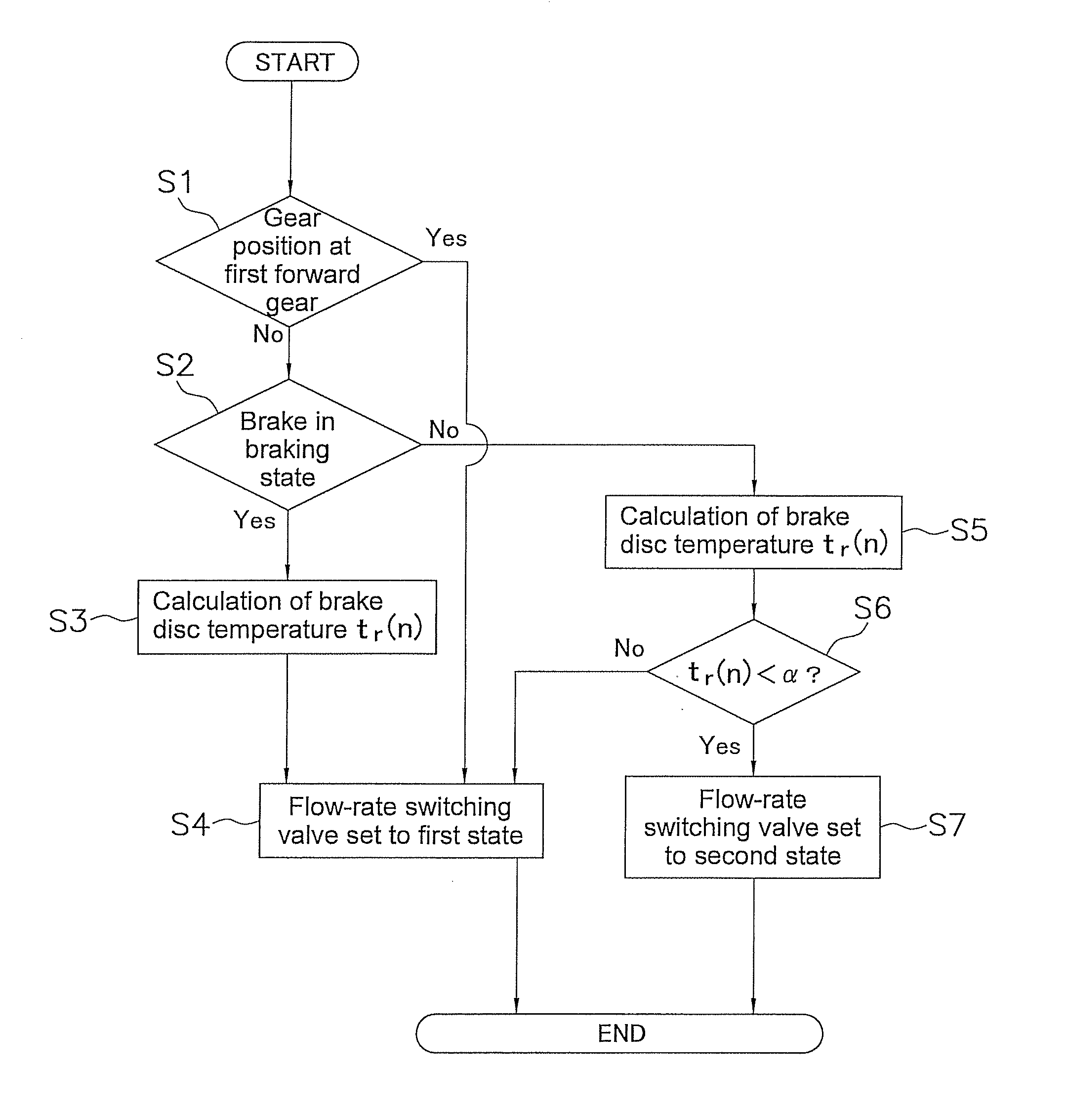
[0089]In the aforementioned embodiment, a decision is made in the first step S1 as to whether the gear position of the transmission 10 is the first forward gear, and in an instance where the gear position of the transmission 10 is the first forward gear, the first control is not executed, and the second control is executed. However, the following decision may be made instead of, or in addition to, the aforementioned decision.

[0090]A decision may be made as to whether the rotating speed of the brake discs 20 exceeds a predetermined value, and the first control is made to be executable when the rotating speed of the brake discs 20 exceeds the predetermined value, while the second control is made to be executable when the rotating speed is equal to or less than the predetermined value.

[0091]In such an instance, the first control is made to be executable when a large suppressing effect on the driving force is exhibited in the braking device 5a, 5b; whereas the first control is not execu...


PUM


Abstract

The work vehicle includes a braking device, a lubricant feeding section, and a controlling section. The controlling section configured to execute a first control in which an amount of the lubricant fed to the braking device is controlled based on a temperature of a rotating member of the braking device. The controlling section sets the amount of the lubricant to a predetermined first feed amount when the braking device is in a braking state, calculates the temperature of the rotating member, and makes a decision in the first control, based on the calculated temperature of the rotating member, to change the amount of the lubricant from the first feed amount to a second feed amount, which is smaller than the first feed amount, when the braking device is switched from the braking state to a non-braking state.

Description

CROSS-REFERENCE TO RELATED APPLICATIONS[0001]This national phase application claims priority to Japanese Patent Application No. 2007-234131, filed on Sep. 10, 2007. The entire disclosure of Japanese Patent Application No. 2007-234131 is hereby incorporated herein by reference.TECHNICAL FIELD[0002]The present invention relates to a work vehicle and a method for controlling the work vehicle.BACKGROUND ART[0003]In a braking device for pressing a rotating member that rotates together with an output shaft against a fixed member fixed to a vehicle body to generate a braking force, the rotating member generates heat due to friction. Therefore, a lubricant is applied between the rotating member and the fixed member, thereby cooling the rotating member and suppressing increase in temperature of the rotating member.[0004]In an instance where there is a large amount of lubricant between the rotating member and the fixed member, there is a possibility that a part of the driving force of the out...

Claims


Application Information

Patent Timeline
Patent Type & Authority Patents(United States)
IPC IPC(8): G06F7/70F16D65/78G06F17/00F16D13/72B60T8/66B60T8/36F16D11/04F16D13/00F16D65/00B60W10/10
CPCB60T5/00F16D65/78F16D2065/783
Inventor KURE, KAZUKISUZUKI, KAZUYUKIYAMAMOTO, SHIGERU
Owner KOMATSU LTD
Why Eureka
Try Eureka