Acoustic fluid machine

a technology of acoustic fluid machine and acoustic compressor, which is applied in the direction of machines/engines, positive displacement liquid engines, pumping machines, etc., can solve the problems of difficult to obtain a stable acoustic compressor, difficult to obtain industrially applicable pressure ratio in linear or conical pipes, etc., to facilitate control of resonance points, reduce waveform strain and variation, stable resonant frequency

Inactive Publication Date: 2007-08-07
ANEST IWATA CORP
View PDF7 Cites 4 Cited by
  • Summary
  • Abstract
  • Description
  • Claims
  • Application Information

AI Technical Summary

Benefits of technology

[0007]In view of the disadvantages in the prior art, it is an object of the present invention to provide an acoustic fluid machine comprising an acoustic resonator to reduce waveform strain and variation in resonant frequency with elevated piston acceleration, thereby achieving stable resonant frequency with respect to driving force amplitude corresponding to operational conditions such as flow rate and pressure as a compressor, to facilitate control in resonance points.

Problems solved by technology

However, it is difficult to obtain industrially applicable pressure ratio in the linear or conical pipe, and resonance area is variable with variation in acceleration of the driving sound source depending on temperature change.
Specifically, resonance points are likely to be shifted, so that it is difficult to keep resonance points, which results in difficulty in obtaining a stable acoustic compressor.

Method used


Image

  • Acoustic fluid machine
  • Acoustic fluid machine
  • Acoustic fluid machine

Examples


Embodiment Construction

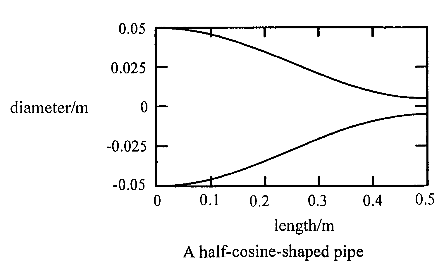
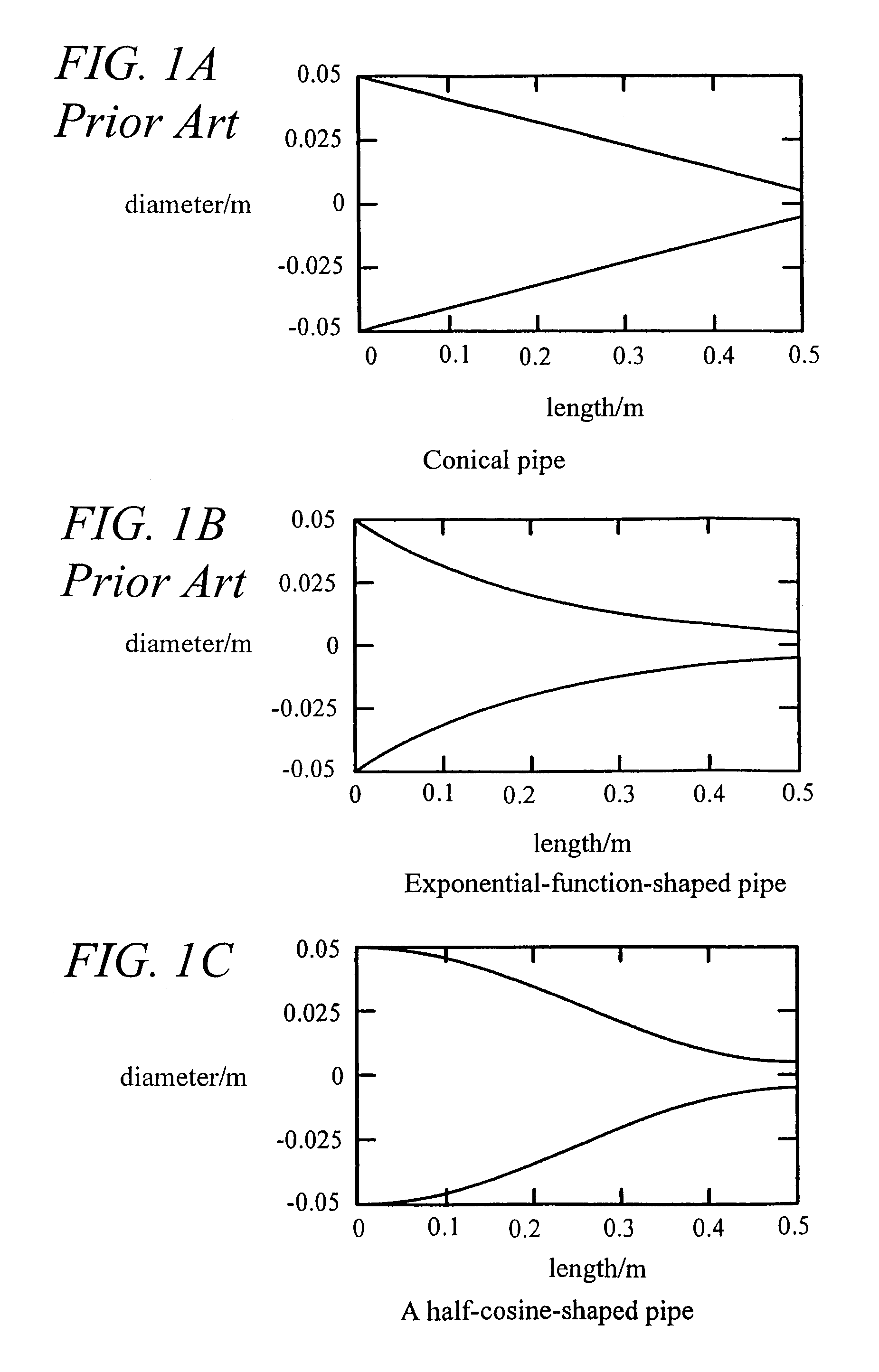
[0019]FIG. 1 shows three types of acoustic resonators in which (a) and (b) are known and (c) is the subject of the present invention.

[0020](a) A conical pipe: Variation rate in diameter axially is constant.

[0021](b) An exponential-function-shaped pipe: Variation rate in diameter at a larger-diameter actuating end is large, while being small at the smaller-diameter suction / discharge end.

[0022](c) A half-cosine-shaped pipe in which the inner surface of the acoustic resonator is defined to comply with the formula of a half-period cosine function: Variation rate in diameter is substantially zero at the larger-diameter actuating end and the smaller-diameter suction / discharge end.

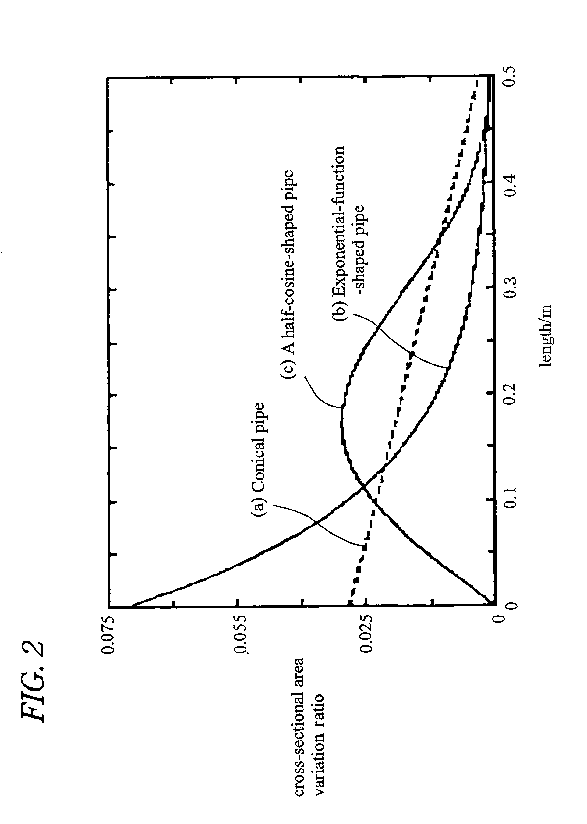
[0023]With respect to the three pipes, variation rate in cross-sectional area in an axial direction is shown in FIG. 2.

[0024]FIG. 2 means the following. In the conical pipe, the cross-sectional area reduces linearly in an axial direction. In the exponential-function-shaped pipe, the cross-sectional area reduces s...


PUM


Abstract

An acoustic fluid machine such as an air compressor comprises an acoustic resonator, a valve device and a piston. Air is sucked into the resonator through the valve device at one end of the resonator. The piston at the other end of the resonator is reciprocated by an actuator to compress the air in the resonator to cause resonance to increase pressure of the air significantly. The inner surface of the resonator is suitably curved to comply with the formula of a half-period cosine function.

Description

BACKGROUND OF THE INVENTION[0001]The present invention relates to an acoustic fluid machine based on pressure variation by acoustic resonance and especially to an acoustic fluid machine suitable for use as an air compressor, a cooling compressor and a vacuum pump.[0002]Recently acoustic compressors have attracted considerable attention, the compressors being grounded on pressure variation of large amplitude standing acoustic waves generated by resonance in acoustic resonators.[0003]An acoustic resonator that is important in an acoustic fluid machine such as an acoustic compressor comprises a linear pipe having an internal constant cross-sectional area in EP 0 447 134 A2, and a conical pipe in which an internal cross-sectional area varies in U.S. Pat. No. 5,319,938 A and EP 0 570 177 A2.[0004]When a linear pipe is used as acoustic resonator, waveform becomes steeper owing to nonlinearity with increase in amplitude to generate propagating shock waves in the acoustic resonator. Thus, i...

Claims


Application Information

Patent Timeline
Patent Type & Authority Patents(United States)
IPC IPC(8): F01N1/14
CPCF04F7/00
Inventor KAWAHASHI, MASAAKIFUJIOKA, TAMOTSUSAITO, MASAYUKI
Owner ANEST IWATA CORP
Why Eureka
Try Eureka