Light source module of light emitting diode

a light-emitting diode and light-emitting diode technology, applied in the direction of semiconductor devices, semiconductor/solid-state device details, electrical apparatus, etc., can solve the problem of inability to reduce the size, achieve the effect of efficient heat dissipation structure, reduce the volume of the light-emitting module, and reduce the siz

Active Publication Date: 2007-08-07
AU OPTRONICS CORP
View PDF4 Cites 31 Cited by
  • Summary
  • Abstract
  • Description
  • Claims
  • Application Information

AI Technical Summary

Benefits of technology

[0008]According to the goal of above description, LEDs are applied in a light source module of the lighting device in the present invention. Wherein the PCB transmitting the input power is isolated at the outside of the heat dissipation of the LED package structure. And the first thermal conductive element is connected thermally to the second thermal conductive element in the LED package structure. Therefore, the light source module only has to apply a conventional PCB to execute the operation of the input power and the heat dissipation structure can be simplified in the LED package structure and then reduce the size of the whole light source module.

Problems solved by technology

However, the size cannot be decreased because the heat dissipation problem and the expensive metal-base printed circuit board (PCB) must be applied in the LED package structure.

Method used


Image

  • Light source module of light emitting diode
  • Light source module of light emitting diode
  • Light source module of light emitting diode

Examples


Embodiment Construction

[0015]The following is the detail description of the present invention. It should be noted and appreciated that the process steps and structures described below does not cover a complete process flow and structure. The present invention can be practiced in conjunction with various fabrication techniques that are used in the art, and only so much of the commonly practiced process steps are included herein as are necessary to provide an understanding of the present invention.

[0016]The present invention will be described in detail with reference to the accompanying drawings. It should be noted that the drawings are in greatly simplified form and they are not drawn to scale. Moreover, dimensions have been exaggerated in order to provide a clear illustration and understanding of the present invention.

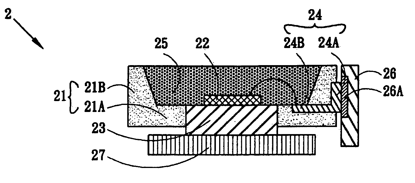
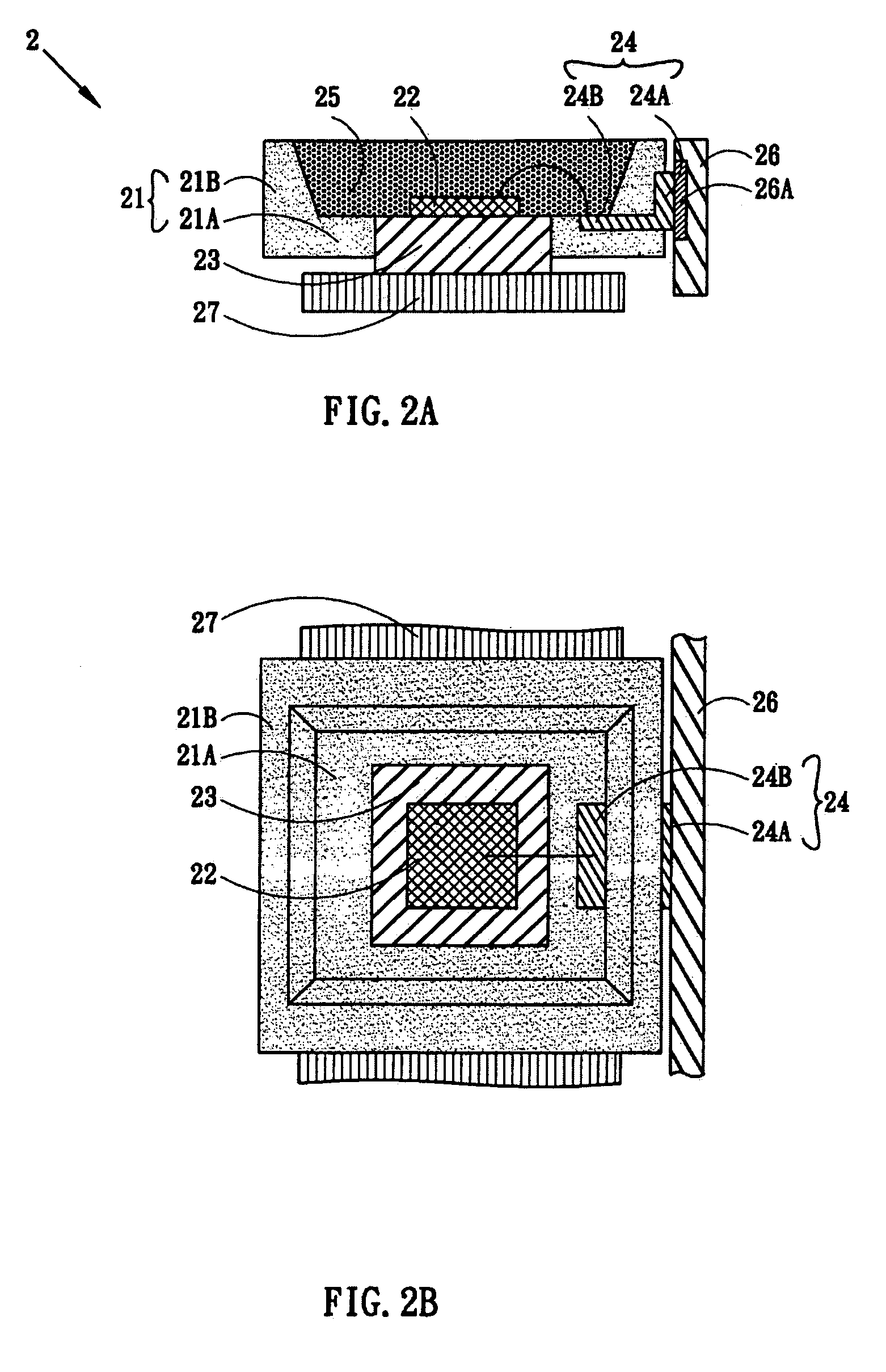
[0017]In a preferred embodiment of the present invention, a light source module of the light emitting diode (LED) 2 is provided which includes an LED package structure and a printed circuit ...


PUM


Abstract

A light source module for a light emitting diode (LED) is provided. In the present invention, a common printed circuit board (PCB) is utilized to provide electric current and isolated from the heat dissipation mechanism, and the thermal conductive element, protruding from the LED package structure, is connected to another thermal conductive element to dissipate out the internal heat.

Description

[0001]This application claims the benefit of Taiwan application Serial No. 94104800, filed Feb. 18, 2005, the subject matter of which is incorporated herein by reference.FIELD OF THE INVENTION[0002]The present invention relates to a light source module, and more particularly relates to a light source module of the light emitting diode (LED).DESCRIPTION OF THE RELATED ART[0003]Light emitting diode (LED) is a common lighting element. It can be used as an instructor light in the electrical products, or the high power LED can be used for lighting, for example, the high power LED is often used as the backlight for the display devices. However, the lighting efficiency and the life of the LED are affected by the design of the heat dissipation of the light source module. When the LED is in high temperature of the working environment, the light output efficiency will be reduced. By increasing the input current of the power merely products more heat but the temperature of the LED increases, a...

Claims


Application Information

Patent Timeline
Patent Type & Authority Patents(United States)
IPC IPC(8): H01L29/22H01L33/48H01L33/62H01L33/64
CPCH01L33/486H01L33/642H01L25/0753H01L33/62H01L2224/48091H01L2224/48247H01L2924/00012H01L2924/00014
Inventor WU, MENG-CHAI
Owner AU OPTRONICS CORP
Why Eureka
Try Eureka