Water supply apparatus

a water supply apparatus and water supply technology, applied in the direction of electric generator control, liquid fuel engines, machines/engines, etc., can solve the problems of cumbersome operation of the power generating mechanism such as the rotary shaft and the blades to the apparatus body, and the loss of power generated by the power generator

Active Publication Date: 2007-08-07
TOTO LTD
View PDF34 Cites 59 Cited by
  • Summary
  • Abstract
  • Description
  • Claims
  • Application Information

AI Technical Summary

Problems solved by technology

That is, water which flows toward the proximal end portions of the blades impedes the rotation of the blades thus giving rise to a loss of amount of power generated by a power generator.
Further, the conventional apparatus adopts the structure in which the rotating shaft is mounted on the apparatus body and does not adopt the structure which allows the detachable mounting of the power generating unit on the apparatus body and hence, an operation to assemble a power generating mechanism such as the rotary shaft and the blades to the apparatus body becomes cumbersome and, at the same time, the maintenance operation of the power generating mechanism also becomes cumbersome.

Method used


Image

  • Water supply apparatus
  • Water supply apparatus
  • Water supply apparatus

Examples


Embodiment Construction

[0036]Hereinafter, the specific structure of the water supply apparatus according to the present invention is explained in conjunction with attached drawings.

(Toilet Bowl Flushing Apparatus)

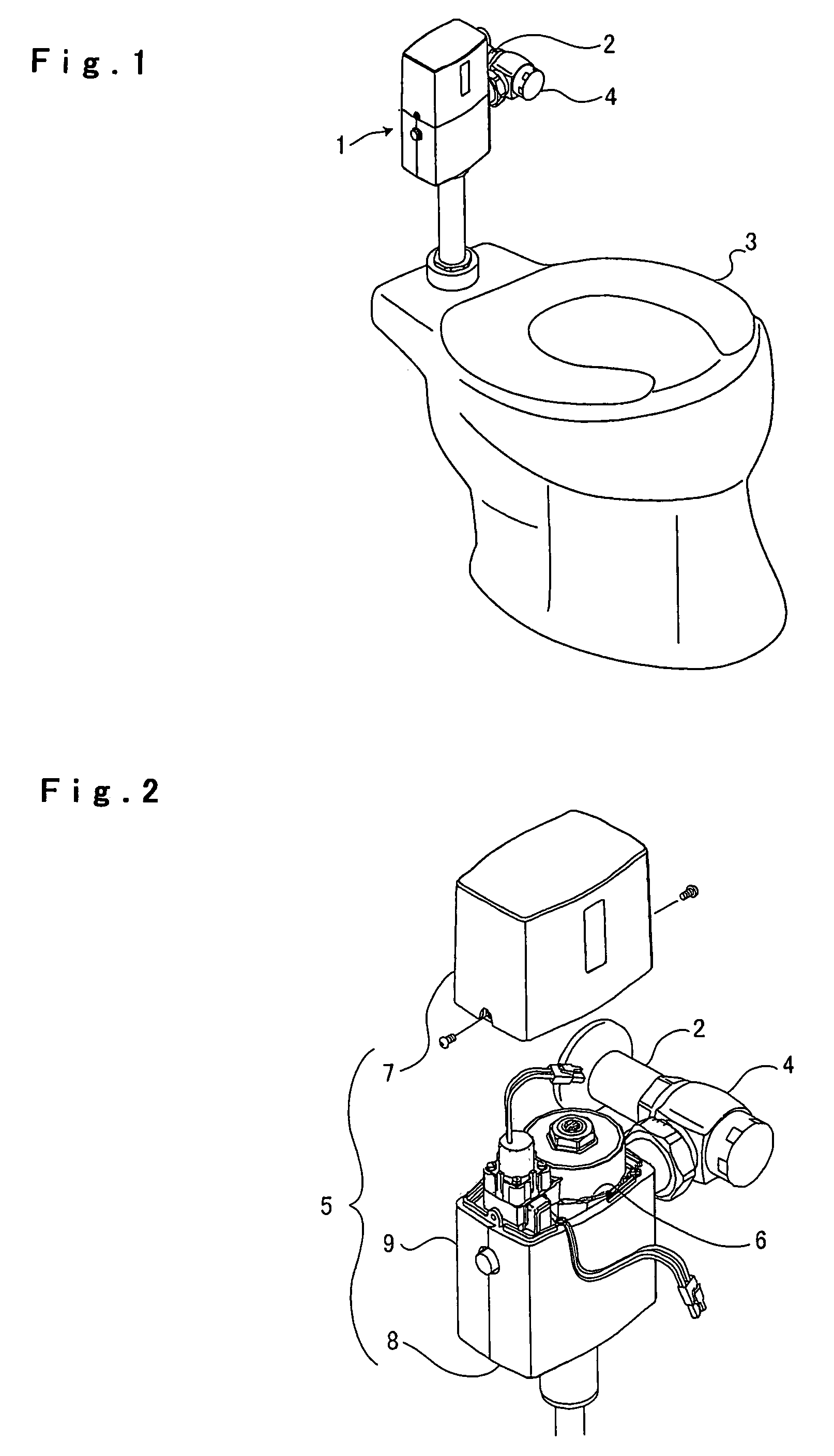
[0037]FIG. 1 shows a toilet bowl flushing apparatus 1 which constitutes a water supply apparatus according to the present invention.

[0038]The toilet bowl flushing apparatus 1 is, as shown in FIG. 1, interposed between a water supply pipe 2 and a toilet bowl 3 and is served for supplying water supplied from a water supply pipe 2 to the toilet bowl 3. In the drawing, numeral 4 indicates a water stop valve. Here, the toilet bowl 3 may be a waste bowl shown in FIG. 1 or a urine bowl shown in FIG. 11.

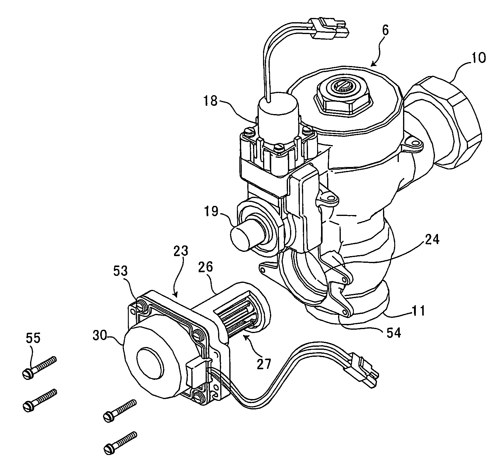
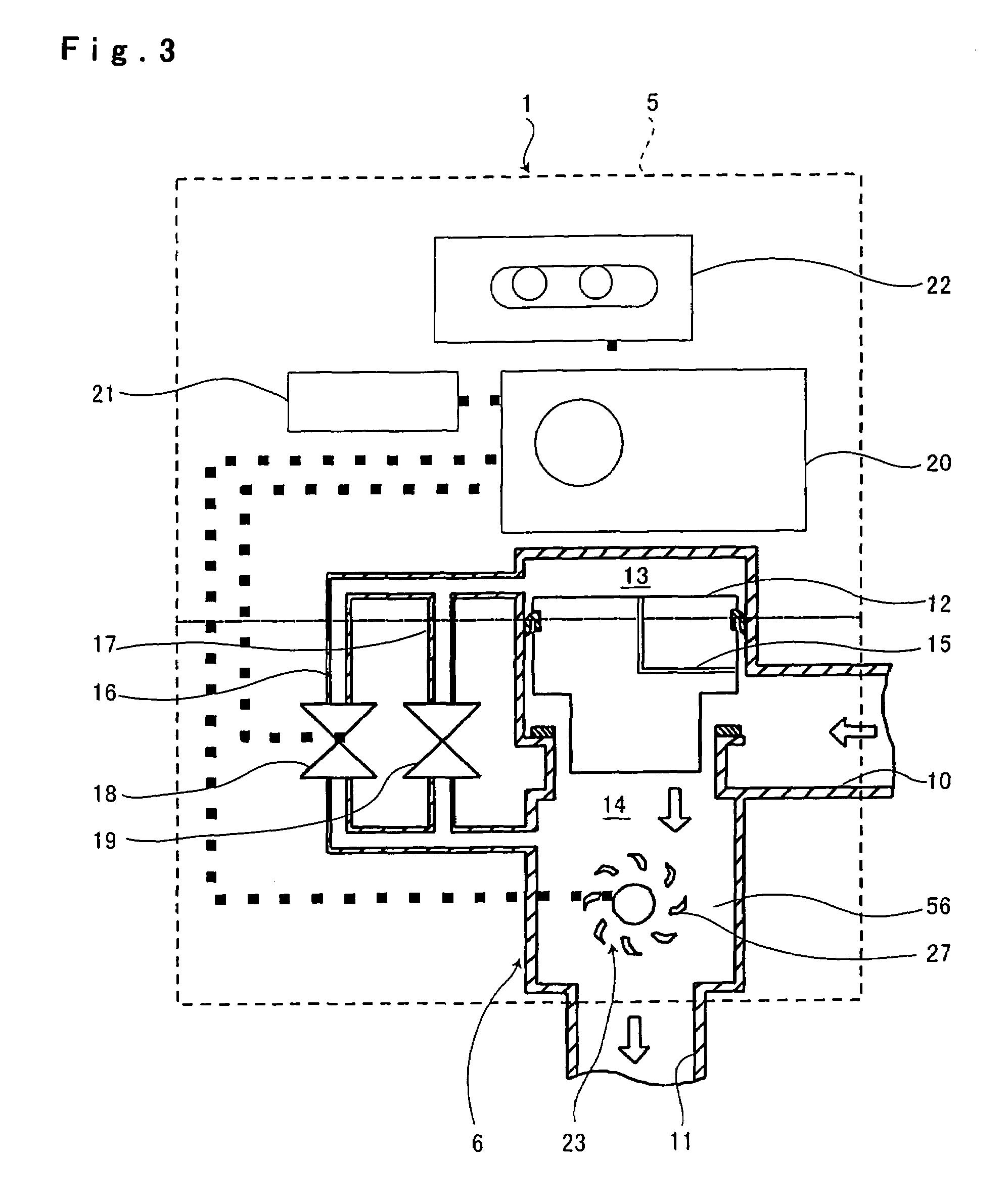
[0039]In the toilet bowl flushing apparatus 1, as shown in FIG. 2, a apparatus body 6 is disposed in the inside of a casing 5.

[0040]As shown in FIG. 2, FIG. 4 and FIG. 5, the casing 5 has the split structure and is constituted of an upper cover 7 which covers an upper portion of the apparatus body 6, a fr...


PUM


Abstract

A water supply apparatus includes an apparatus body disposed in a flow passage for sucking water to an indoor facility and a power generation unit installed in the apparatus body. Further, the power generation unit further comprises a rotating shaft extended in a direction perpendicular to the water channel direction of the flow passage, and impeller installed on the rotating shaft and rotated by a water flow, a magnet rotated interlockingly with the impeller, and a coil arranged oppositely to the magnet, wherein the impeller forms blades in the radial outer direction and forms clearances allowing water to pass to the inside of the blades. Since the clearances are formed between the blades and the rotating shaft such a trouble that water flowing into the base ends of the blades obstructs the rotation of the impeller can be eliminated to increase a power generation amount by the power generation unit. In addition, since there is no need to expand the flow passage on the outside of the impeller to reduce the rotational resistance of the impeller, the size of the water supply apparatus can be reduced.

Description

TECHNICAL FIELD[0001]The present invention relates to a water supply apparatus which installs a power generating unit in a midst of a flow passage which supplies water to an indoor facility. Here, the indoor facility indicates a water-related facility such as a sink, a wash basin, a toilet bowl, a washing machine or the like which are used in public facilities such as offices and stations and residences and is also a facility which uses service water, intermediate water, sewage, well water, rains and the like.BACKGROUND ART[0002]Conventionally, a water supply apparatus which installs a power generating unit in a midst of a flow passage for supplying water to an indoor facility has been popularly used. In such a water supply apparatus, the power generating unit generates an electric power by making use of a water flow in the inside of the flow passage and various electronic equipment such as sensors and switches which are mounted inside or outside the water supply apparatus are drive...

Claims


Application Information

Patent Timeline
Patent Type & Authority Patents(United States)
IPC IPC(8): F03B13/00F03B13/10H02P9/04E03D3/00
CPCE03D3/00F03B13/00F05B2220/602Y02B10/50Y02E10/28Y02E10/20
Inventor FUJIMOTO, HIDEFUMIONODERA, NAOYUKINAKAYAMA, KIMIHIROHATAKEYAMA, MAKOTOENOMOTO, KAZUYUKIKUDOH, YUKIHIROKUGA, TATSUHIROISHIMARU, SATOSHI
Owner TOTO LTD
Why Eureka
Try Eureka