
Curvature corrected bandgap reference circuit and method

a reference circuit and curvature correction technology, applied in the direction of power supply lines, instruments, vehicle components, etc., can solve the problems of “bandgap curvature” error in output voltage, and inability to meet the demand for low power and low voltage operation. , to achieve the effect of small overhead voltage and small total resistan

Active Publication Date: 2007-08-07
ANALOG DEVICES INC
View PDF16 Cites 37 Cited by
  • Summary
  • Abstract
  • Description
  • Claims
  • Application Information

AI Technical Summary

Benefits of technology

The present invention provides a reference circuit and method that compensates for bandgap curvature error with a low overhead voltage and small total resistance. The circuit includes two bipolar transistors with different base-emitter voltages that have operating currents that vary with temperature. The ratio of current densities in the transistors changes with temperature, resulting in a residual component that compensates for bandgap curvature error. The circuit is designed to maintain the same ratio of currents regardless of temperature, and the residual component is adjusted to compensate for bandgap curvature error. The invention provides a more accurate reference voltage for use in electronic circuits.

Problems solved by technology

However, there is an ever-increasing demand for low power and low voltage operation, which may make this limitation unacceptable.
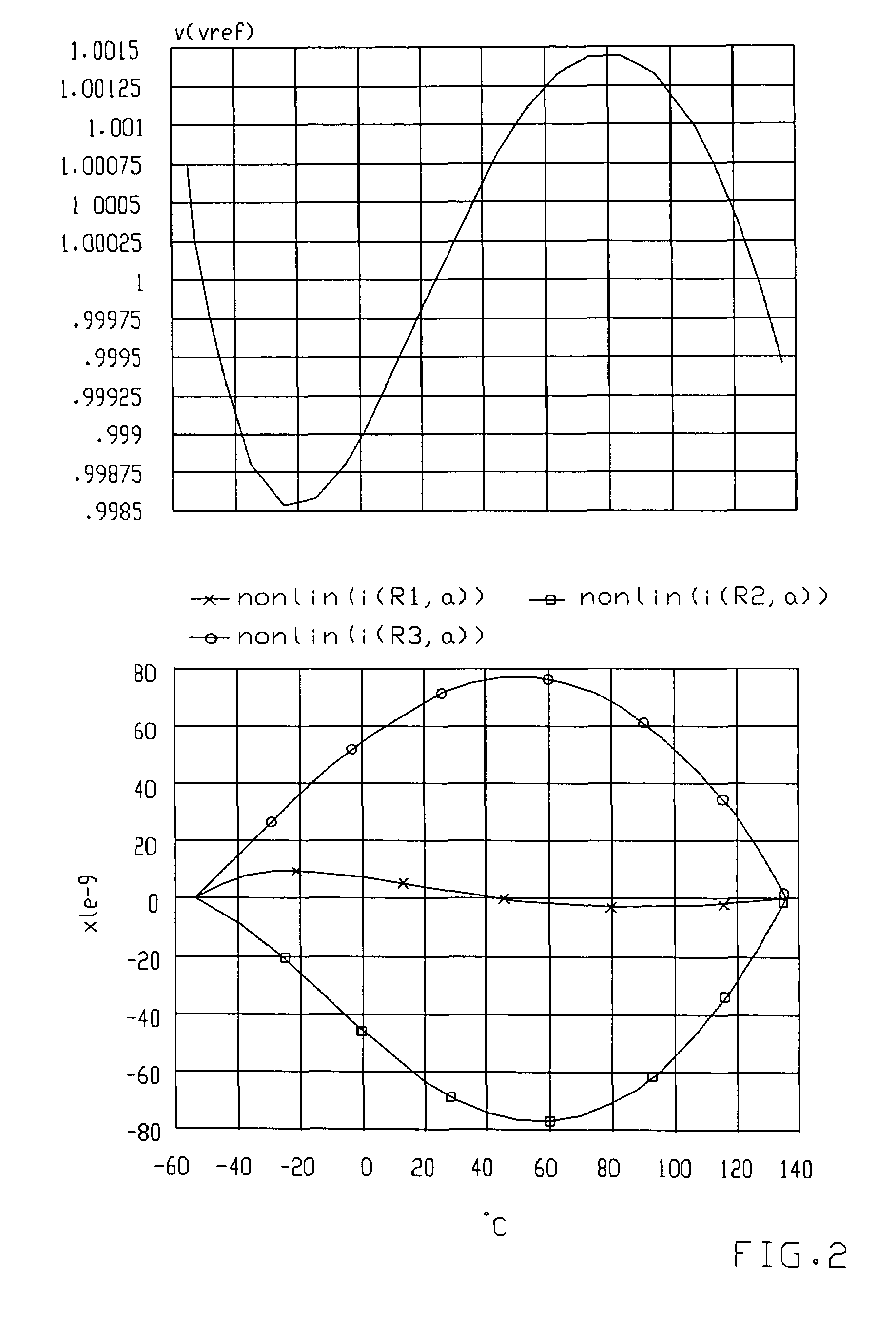
This nonlinearity results in a “bandgap curvature” error in the output voltage which varies over temperature.
The circuit described in Banba does not address this error, and as such, its reference voltage output may not be adequate for some applications.
However, the additional components have relatively large values and require relatively large areas, adding cost and complexity to the design.

Method used


Image

  • Curvature corrected bandgap reference circuit and method
  • Curvature corrected bandgap reference circuit and method
  • Curvature corrected bandgap reference circuit and method

Examples


Embodiment Construction

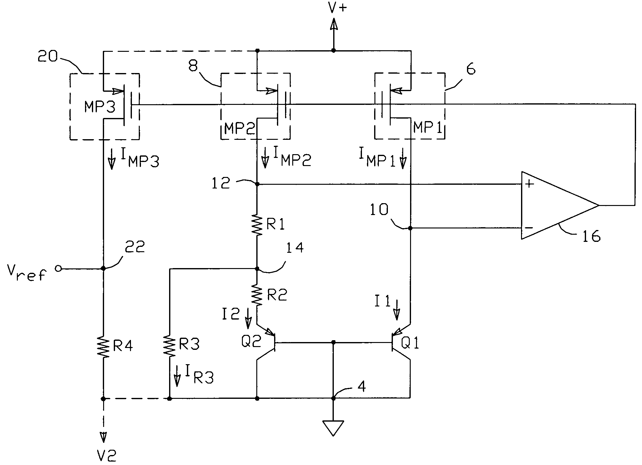
[0020]The present curvature corrected bandgap reference circuit requires operating a first bipolar transistor (Q1) having a base-emitter voltage Vbe1 such that it has a constant operating current, and operating a second bipolar transistor (Q2) having a base-emitter voltage Vbe2 such that it has an operating current consisting of an approximately temperature proportional component and a non-linear component. This results in a ratio of current densities in Q1 and Q2 which varies with temperature. When properly arranged, the difference voltage ΔVbe=Vbe1−Vbe2 will include a residual component of the form:

(kT / q)ln((T0−Tx) / (T−Tx)),

where T0 is a normalizing measurement temperature and Tx is the zero intercept of the temperature proportional component; this residual component can be used to approximately compensate bandgap curvature error.

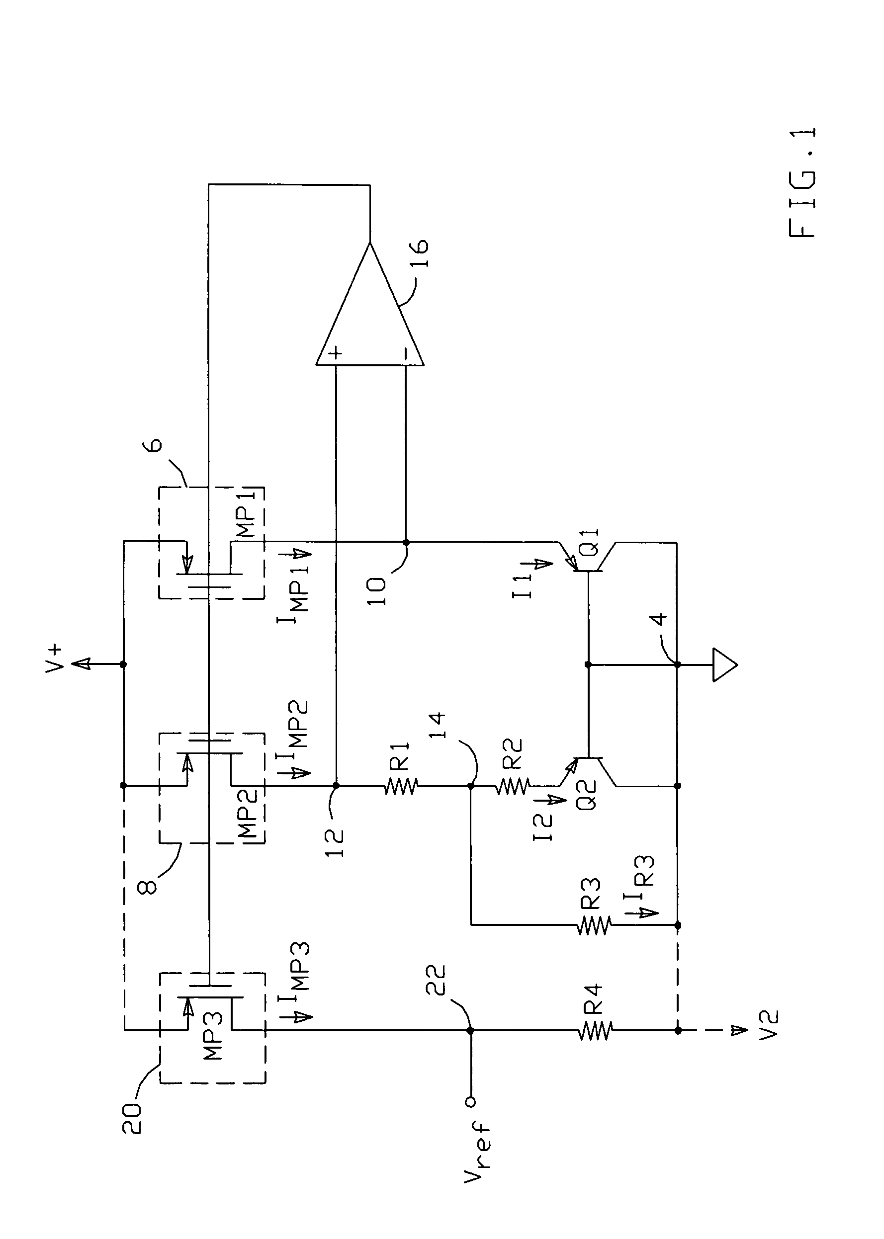
[0021]One possible circuit-embodiment which implements this approach is shown in FIG. 1. The circuit includes first and second bipolar transistors (Q1, Q2...


PUM


Abstract

A curvature corrected bandgap reference circuit comprises a first bipolar transistor having a base-emitter voltage Vbe1 and operated such that it has a constant operating current, and a second bipolar transistor having a base-emitter voltage Vbe2 and operated such that it has an operating current consisting of an approximately temperature proportional component and a non-linear component. The circuit is arranged such that the ratio of the current densities in the two transistors varies with temperature, such that the difference voltage (ΔVbe=Vbe1−Vbe2) includes a residual component which approximately compensates bandgap curvature error.

Description

[0001]This application claims the benefit of provisional patent application No. 60 / 550,590 to Brokaw, filed Mar. 4, 2004.BACKGROUND OF THE INVENTION[0002]1. Field of the Invention[0003]This invention relates to the field of bandgap voltage reference circuits, and particularly to circuits and methods that compensate for the bandgap curvature term in the outputs of such circuits.[0004]2. Description of the Related Art[0005]Voltage reference circuits generate one or more reference voltages that are ideally stabilized over process, supply voltage, and temperature variations. Reference circuits which create an output based on the bandgap voltage of silicon largely achieve these ideals, and are one of the most popular types of voltage reference circuit.[0006]The output of a conventional bandgap reference circuit is about 1.25 volts. This typically requires that the supply voltage for the reference circuit be no lower than 1.25 volts. However, there is an ever-increasing demand for low pow...

Claims


Application Information

Patent Timeline
Patent Type & Authority Patents(United States)
IPC IPC(8): G05F3/16
CPCG05F3/30Y10S323/907
Inventor BROKAW, A. PAUL
Owner ANALOG DEVICES INC
Learn More