Eureka AIR delivers breakthrough ideas for toughest innovation challenges, trusted by R&D personnel around the world.

Biometric sensor apparatus and methods

a biometric sensor and sensor technology, applied in the field of biometric sensors and methods, can solve the problems of method spoofed, affecting capacitance, and expensive implementation

Active Publication Date: 2007-08-07
STMICROELECTRONICS (RES & DEV) LTD
View PDF6 Cites 51 Cited by
  • Summary
  • Abstract
  • Description
  • Claims
  • Application Information

AI Technical Summary

Problems solved by technology

However, such methods can still be spoofed, for example by rubber models of a finger.
Properties of a live finger such as perspiration, warmth, and pressure, mean that the conductivity of the ridges will change, thus affecting the capacitance.
However, they are expensive to implement.

Method used


Image

  • Biometric sensor apparatus and methods
  • Biometric sensor apparatus and methods

Examples


Embodiment Construction

[0010]The invention will be described in relation to systems for biometric identification based on fingerprints, but is also applicable to identification based on unique characteristics of other body members, particularly hand or palm prints.

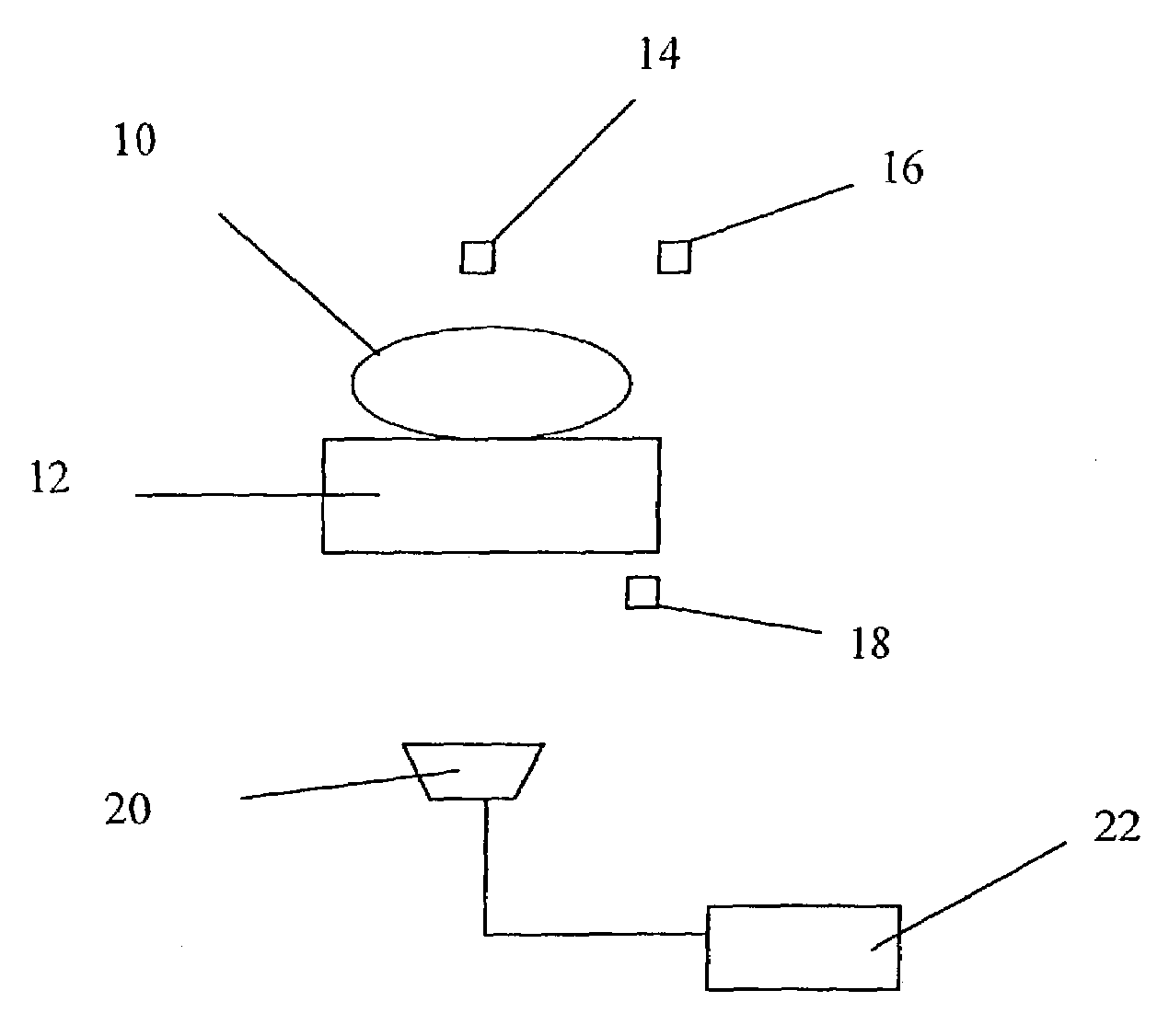
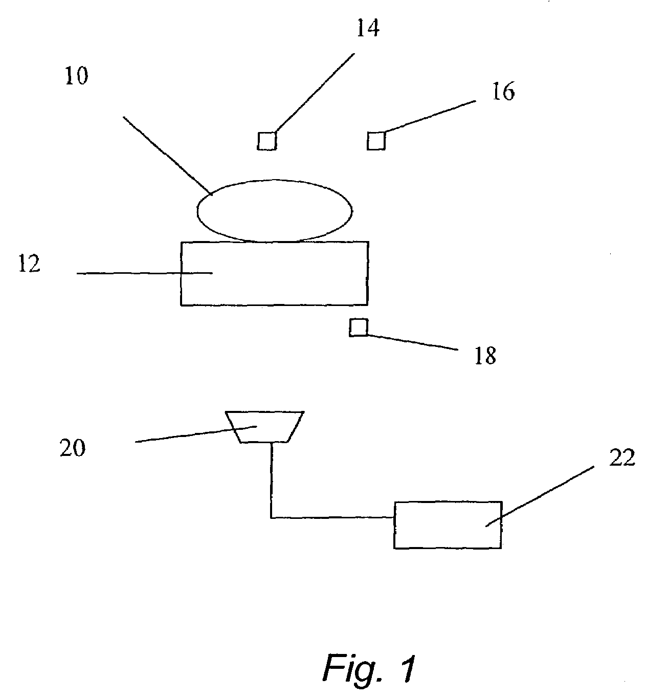
[0011]As shown in FIG. 1, a preferred embodiment of a biometric identification system in accordance with the invention is adapted to read and analyze a fingerprint of a fingertip 10 placed in contact with a translucent platen 12. It will be evident to those skilled in the art that in this context the term “translucent” includes the case where the platen 12 is in fact transparent. At least a first and preferably first and second IR illumination sources 14 and 16, suitably light emitting diodes (LEDs), are arranged above the platen 12 to transmit light of selected frequencies in the IR band through the fingertip 10 and platen 12. At least a first visible illumination source 18, again suitably an LED, is arranged below the platen 12 to transmit vis...


PUM


Abstract

The optical biometric sensor apparatus and methods for analyzing images of biometric features such as fingerprints are adapted to distinguish between live body members and inanimate objects, and to detect spoofing devices applied to live body members. Live body members are detected by transmitting IR light from a first IR light source through an object to an image sensor. The IR transmission characteristics of a live body member vary with the human heartbeat, and multiple images are analyzed to verify whether the object is a genuine live body member. A visible light source illuminates the object for obtaining a detailed image from the sensor for conventional biometric analysis. Transmitted IR images and reflected visible light images are also processed to detect the presence of spoofing devices applied to live body members. Multiple IR and visible light sources of different wavelengths may be used for this purpose.

Description

FIELD OF THE INVENTION[0001]The present invention relates to biometric sensors and methods. More particularly, the invention relates to devices and methods using optical imaging of fingerprints, handprints or the like to verify a person's identity, and which are resistant to “spoofing”. The invention is particularly concerned with determining whether a finger, hand or the like presented to a biometric imaging device is a live finger, hand etc.BACKGROUND OF THE INVENTION[0002]To be secure, identification systems need to be robust against fraud; i.e. to ensure that one person cannot pass themselves off as another person.[0003]The field of biometrics relates to the statistical analysis of physiological characteristics. For the purposes of identification for security or other purposes, features such as fingerprints or retinal scans can be used to uniquely identify individuals. Every person has a unique set of fingerprints, and this provides a basis for identification. An image of a fing...

Claims


Application Information

Patent Timeline
Patent Type & Authority Patents(United States)
IPC IPC(8): G06K9/00G06V40/13
CPCG06K9/00013G06K9/00114G06V40/1388G06V40/13
Inventor DENNIS, CARL
Owner STMICROELECTRONICS (RES & DEV) LTD
Why Eureka
Eureka Blog
Learn More