Air mattress

a mattress and air technology, applied in the field of air mattresses, can solve the problems of loss of recovery force, difficult for users to maintain proper posture, and inability to maintain an inherent shape of the mattress

Inactive Publication Date: 2007-08-14
KIM WORL SUNG
View PDF30 Cites 52 Cited by
  • Summary
  • Abstract
  • Description
  • Claims
  • Application Information

AI Technical Summary

Benefits of technology

[0008]Accordingly, it is an object of the present invention to provide an air mattress which is capable of preventing a side portio

Problems solved by technology

As the time of use of the above mattress increases, the electric force of the wire spring may decrease, so that a recovering force may be lost.
So, it is impossible to maintain an inherent shape of the mattress.
When a user lies on the conventional mattress, an over pressure could be applied to the portions of the mattress contacting with a user's body since the elastic force of the wire spring installed in the interior of the mattress is not uniformly applied to the entire portions of a user'

Method used


Image

  • Air mattress
  • Air mattress
  • Air mattress

Examples


first embodiment

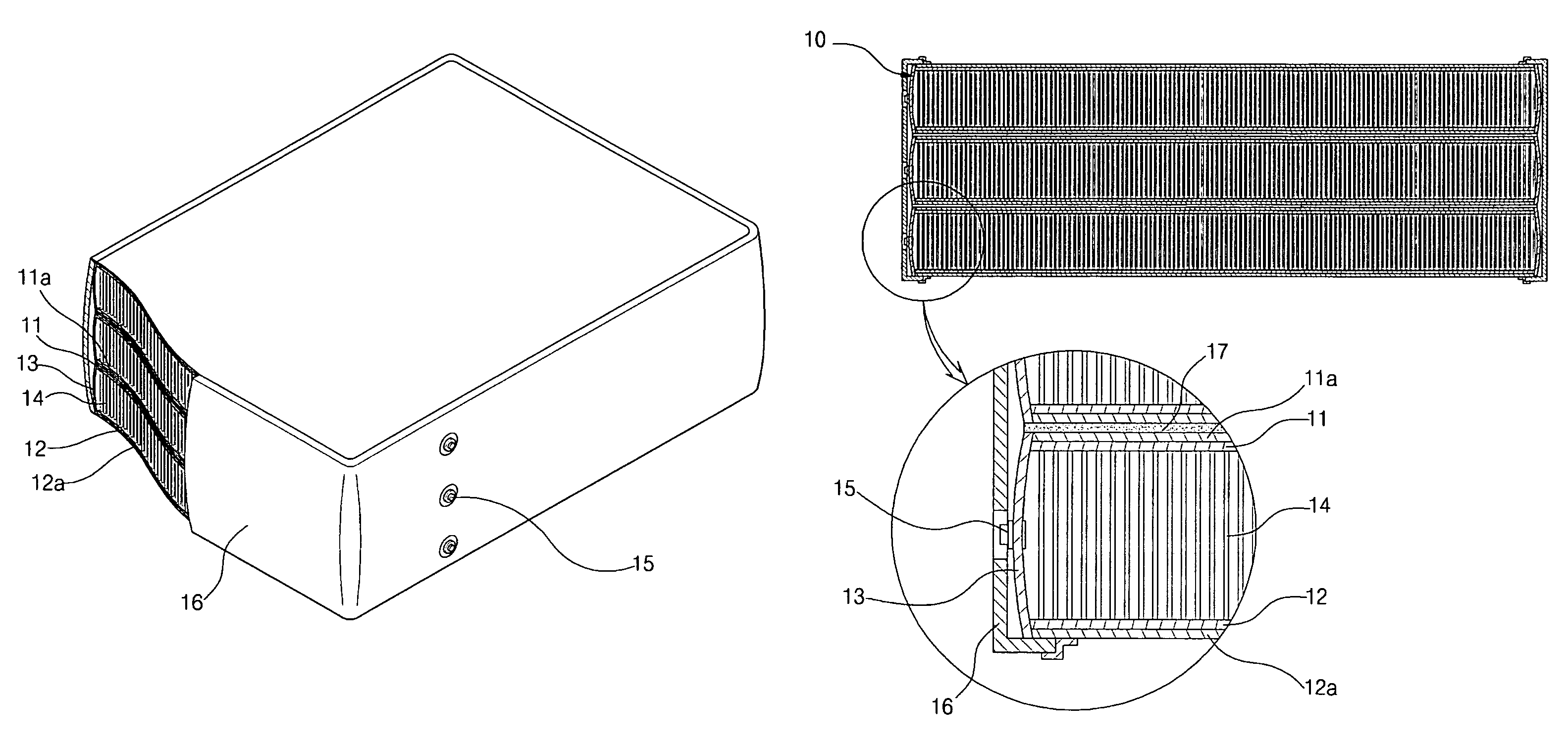
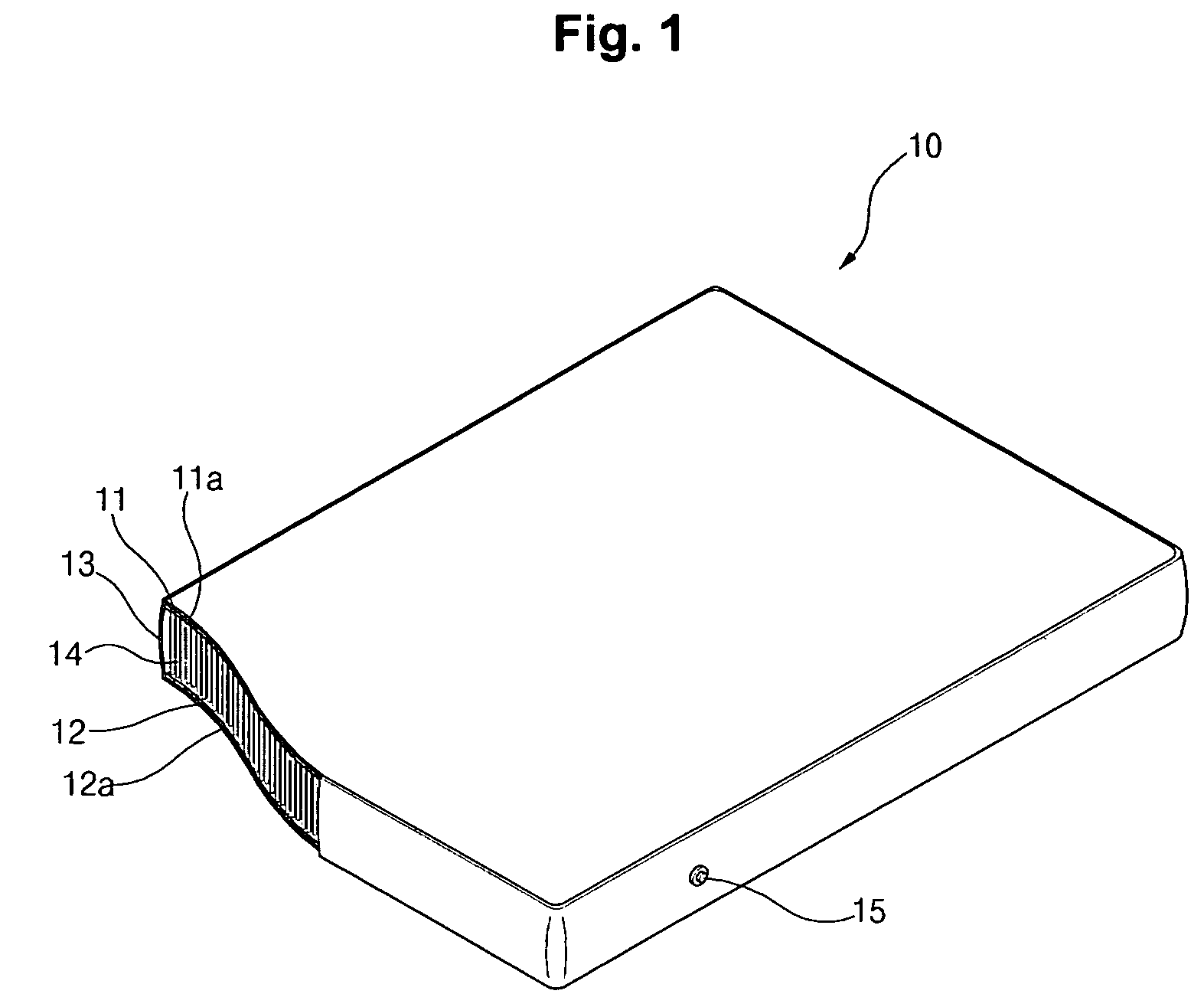
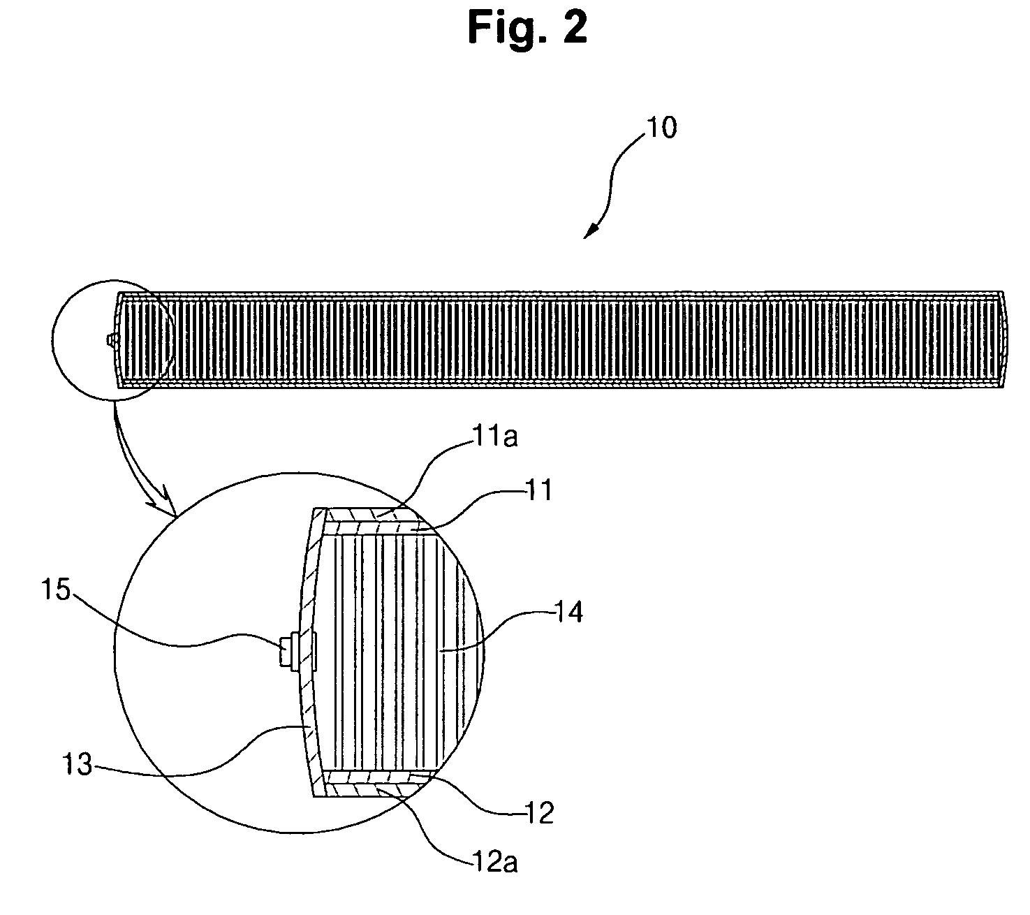
[0018]FIG. 1 is a partially cut-away perspective view illustrating part of an air mattress according to the present invention, and FIG. 2 is a cross sectional view illustrating an air mattress of FIG. 1.

[0019]As shown therein, the air mattress according to the present invention comprises an upper raw material member 11 and a lower raw material member 12.

[0020]Here, the upper raw material member 11 and the lower raw material member 12 are formed of a textile such as a non-woven fabric, etc. A certain quantity of fiber threads is vertically sewed between the upper raw material member 11 and the lower raw material member 12 so as to effectively cope with pressure or transformation externally applied to the mattress.

[0021]A mattress body 10 is formed so that a side raw material 13 formed of a certain raw material is fixedly provided at the opened side portions between the upper raw material member 11 and the low raw material 12.

[0022]Here, coating layers 11a and 12a are formed at the up...

second embodiment

[0031]FIG. 4 is a partially cut-away perspective view illustrating part of an air mattress according to the present invention, and FIG. 5 is a cross sectional view illustrating an air mattress of FIG. 4.

[0032]As shown therein, the air mattress according to the second embodiment of the present invention is formed in a three-layer structure whereas the air mattress according to the first embodiment of the present invention is formed in one-layer structure.

[0033]One mattress body 10 basically includes an upper raw material member 11 which has a coating layer 11a on its upper surface, a lower raw material member 12 which is spaced and formed at a lower side of the upper raw material member 11 and has a coating layer 12a on its lower surface, a plurality of fiber threads 14 which connect the upper raw material member 11 and the lower raw material member 12, a side raw material 13 which is sealingly bonded to a surrounding portion between the upper raw material member 11 and the lower raw...


PUM


Abstract

An air mattress is disclosed, which comprises an upper raw material member which has a coating layer at an upper surface of the same; a lower raw material which is spaced and installed at a lower side of the upper raw material member and has a coating layer at a lower surface of the same; a plurality of fiber threads which vertically connect the upper and lower raw material members and react with respect to an external pressure; a coated side raw material which is fixedly engaged to seal a surrounding portion between the upper and lower raw material members; and an air injection valve engaged at one side of the side raw material. A force distribution function is excellently performed when an external impact is applied to the air mattress according to the present invention, so that a distortion phenomenon of the product is prevented. It is possible to prevent the sides of the air mattress from being abnormally expanded by the side raw material bonded to the upper raw material member and the lower raw material member.

Description

BACKGROUND OF THE INVENTION[0001]1. Field of the Invention[0002]The present invention relates to an air mattress, and in particular to an air mattress which is capable of preventing a side portion of the same from being expanded by an air pressure.[0003]2. Description of the Background Art[0004]Generally, a mattress having a wire spring therein has been largely used as a bed mattress. As the time of use of the above mattress increases, the electric force of the wire spring may decrease, so that a recovering force may be lost. So, it is impossible to maintain an inherent shape of the mattress.[0005]When a user lies on the conventional mattress, an over pressure could be applied to the portions of the mattress contacting with a user's body since the elastic force of the wire spring installed in the interior of the mattress is not uniformly applied to the entire portions of a user's body, namely, only certain portions of the user's body are contacted.[0006]Therefore, it is very hard fo...

Claims


Application Information

Patent Timeline
IPC IPC(8): A47C27/10
CPCA47C27/081A47C27/087A47C27/10Y10S5/932A47C27/08
Inventor KIM, WORL SUNG
Owner KIM WORL SUNG
Why Eureka
Try Eureka