Milking system, a teat cup and a teat cup liner

a technology of teat cup and teat cup, which is applied in the field of milking, can solve the problems of too many teat cups, too many time-consuming and inefficient solutions, and the inability to mimic the lifelike extraction of milk by a calf, and achieve the effect of less service and maintenance work and fewer components

Inactive Publication Date: 2011-05-12
DELAVAL HLDG AB
View PDF8 Cites 7 Cited by
  • Summary
  • Abstract
  • Description
  • Claims
  • Application Information

AI Technical Summary

Benefits of technology

[0017]In accordance with still another embodiment of the invention, the teat cup comprises an inlet connector provided with a protruding part, which protrudes to within the teat cup. A simple means is provided for preventing the teat cup liner from expanding more than desired, i.e. expanding so that the teat and the teat cup liner loses contact with each other.
[0018]In accordance with yet another embodiment of the invention, a non-pulsating vacuum is applied to the teat, whereby a more cost-efficient milking system requiring fewer components and less service and maintenance work, is provided.

Problems solved by technology

The milking systems have been designed to be as natural as possible, but a lifelike mimicking of the milk extraction by a calf is not possible due to efficiency requirements in machine milking systems.
For example, although it would probably be comfortable for a cow to have milk extracted from one teat at a time, and changing teat with a frequency equal to the frequency used by a calf, this would be a too time-consuming and inefficient solution.
It has been noted that the vacuum causes blood and tissue fluids to accumulate in tissue of the tip of the teat, or teat end, causing the teat end to get congested.
The tissue volume may be doubled during milking and the accumulation of fluids in the teat end causes a local circulation disturbance.
The fluid accumulations and tissue swelling in turn cause the teat canal to contract, which leads to a reduced milk flow.
When the teat cup crawls upwards on the teat towards the udder this may cause a cut-off of the milk canal interior of the teat close to the udder, which is uncomfortable for the milking animal and disturbs the milking.
Further, due to ill-fit there may also be a higher pressure on the teat at certain points near the teat end, again causing discomfort.
Moreover, when the udder pressure decreases and becomes low, the contact pressure between liner and teat disappears, which leads to crawling of the teat cup and an abrupt ending of the milking of that teat, leaving residual milk in the udder.
Further yet, the crawling may also result in milk flowing from a short milk tube connected to the teat cup back up into the teat cup, due to the fact that the displaced teat cup liner prevents the normal air leakage around the top of the teat cup and creates a higher vacuum in the teat cup than in the short milk tube.
Besides being painful for the milking animal, this poses a health risk to her as this leads to a higher risk of mastitis bacteria entering the teat canal.
Although much research has been done, it is difficult to design a system providing the best compromise between the wellbeing of the milking animal and the efficiency of the milking system.

Method used


Image

  • Milking system, a teat cup and a teat cup liner
  • Milking system, a teat cup and a teat cup liner
  • Milking system, a teat cup and a teat cup liner

Examples


first embodiment

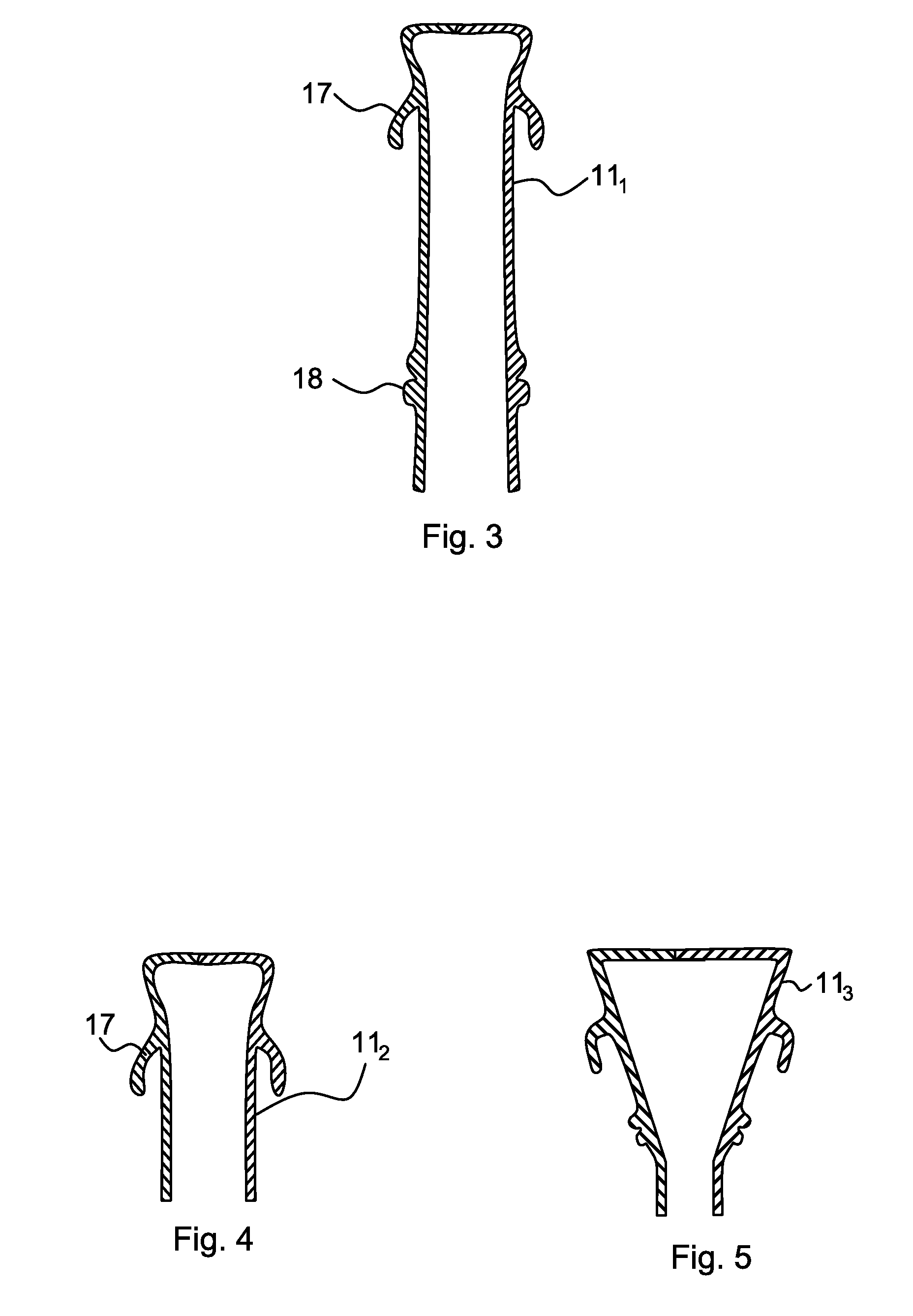
[0034]FIG. 3 illustrates the teat cup liner 111 in accordance with the invention. The shape of the teat cup liner 111 is similar to a conventional teat cup liner, i.e. it comprises attachment means 17, 18 (schematically shown) for mounting to the teat cup shell 10 at the upper end, and at the lower end, respectively. The connection means 17, 18 should be designed so as to enable the closed space 16 to be formed. The teat cup liner 111 may also comprise connection means for connection to a milk line.

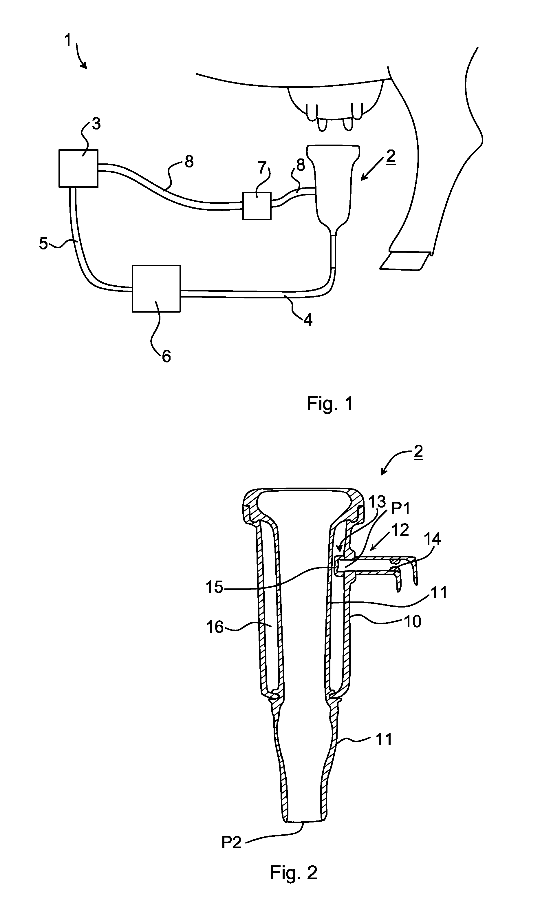
[0035]When the teat cup 2 is to be attached to the teat, a vacuum is supplied at the first connection point P1. The teat cup liner 111 is thereby expanded so that the attachment is accomplished. The lower, rounded part of the teat, i.e. the teat tip, is subjected to the vacuum level supplied at the second connection point P2.

[0036]The diameter of the teat cup liner 111 is chosen so that it, in its relaxed state, i.e. non-contracted and non-expanded state, is smaller than the outer diamete...

third embodiment

[0046]FIG. 5 illustrates the teat cup liner 113. The teat cup liner 113 comprises a conical shape having an upper part that is broader than a lower part. By means of the conical shape the upper part of the teat cup liner 113 bears free from the teat throughout a whole milking session. Further, the lower part of the teat cup liner 113 supports the teat and fits tight only at the lower part of the teat, thereby subjecting only the lower, rounded part of the teat to the vacuum level provided by the vacuum supply source 3.

[0047]The conical shape and in particular the angle between a vertical line and the wall of the teat cup liner 113, i.e. the difference in diameter of the upper part and diameter of the lower part, can be chosen so as to fit all sizes of teats of the milking animals of a herd. The teat cup liner 113 having a certain angle then comes in supporting contact with the teat and fits tight at different heights along the teat, depending on teat size.

[0048]In this embodiment of...


PUM


Abstract

A milking system (1) includes a vacuum supply source (3) and a teat cup (2). The teat cup (2) includes a teat cup liner (11) and a teat cup shell (10), with the teat cup shell (10) connected at plural points to the vacuum supply source (3). The teat cup liner (11) is arranged to support and fit tight to a teat of a milking animal throughout a milking session, whereby a uniform pressure is applied to the teat throughout the milking session so that a milking that is more comfortable for the milking animal is accomplished.

Description

FIELD OF THE INVENTION[0001]The invention relates generally to the field of milking, and in particular to milking systems comprising teat cups with teat cup liners.BACKGROUND OF THE INVENTION[0002]Machine milking was developed in order to alleviate the labour involved in milking. The milking systems have been designed to be as natural as possible, but a lifelike mimicking of the milk extraction by a calf is not possible due to efficiency requirements in machine milking systems. For example, although it would probably be comfortable for a cow to have milk extracted from one teat at a time, and changing teat with a frequency equal to the frequency used by a calf, this would be a too time-consuming and inefficient solution.[0003]In today's milking, a teat cup used for extracting milk comprises a teat cup liner designed to collapse cyclically against the teat by means of a pulsator that alternates between subatmospheric pressure and atmospheric pressure. Such vacuum application causes t...

Claims


Application Information

Patent Timeline
Patent Type & Authority Applications(United States)
IPC IPC(8): A01J5/04A01J5/007
CPCA01J5/08
Inventor PETTERSON, TORBJORN
Owner DELAVAL HLDG AB
Why Eureka
Try Eureka