
Roller tool and positional pressure method of use for the forming and joining of sheet material

a technology of positional pressure and roller tool, which is applied in the direction of manufacturing tools, metal rolling arrangements, metal working apparatuses, etc., can solve the problems of limiting the speed of a roller-forming tool equipped with a pneumatic system to 200 mm/sec, and the difficulty in controlling the variable pressure required by the tool,

Active Publication Date: 2007-08-14
MODERN BODY ENG CORP
View PDF5 Cites 80 Cited by
  • Summary
  • Abstract
  • Description
  • Claims
  • Application Information

AI Technical Summary

Benefits of technology

Enables faster and more precise control of pressures during the forming and joining process, accommodating various panel sizes and shapes, and allowing for higher production speeds beyond the limitations of previous technologies, ensuring accurate and repeatable seam formation.

Problems solved by technology

An unfortunate feature of forming and joining materials with the roller-forming tool is the difficulty in controlling the variable pressures required by the tool.
However, the reaction time for pneumatic compressions and decompressions required for stabilization is finite, limiting the speed of a roller-forming tool equipped with a pneumatic system to 200 mm / sec.
This speed limitation allows for what is known in the art as low volume production only.
However, this sampling does not allow for mechanical compliance of either the forming tool or the servo positioning system.
This latter approach is clearly the least desirable.
Accordingly, prior approaches have failed to solve the speed limit problem associated with the control of the variable pressures required when forming and joining sheet materials at speeds over 200 mm / sec.

Method used


Image

  • Roller tool and positional pressure method of use for the forming and joining of sheet material
  • Roller tool and positional pressure method of use for the forming and joining of sheet material
  • Roller tool and positional pressure method of use for the forming and joining of sheet material

Examples


Embodiment Construction

[0029]The drawings disclose the preferred embodiment of the present invention. While the configurations according to the illustrated embodiment are preferred, it is envisioned that alternate configurations of the present invention may be adopted without deviating from the invention as portrayed. The preferred embodiment is discussed hereafter.

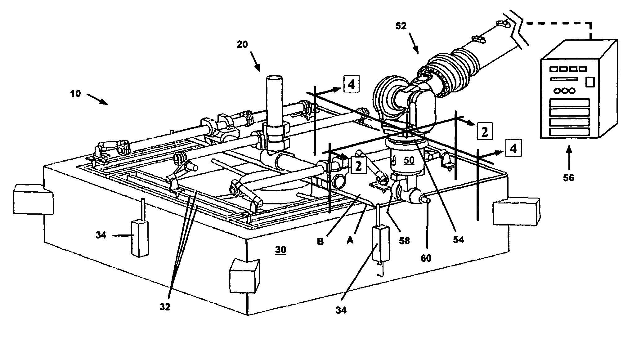
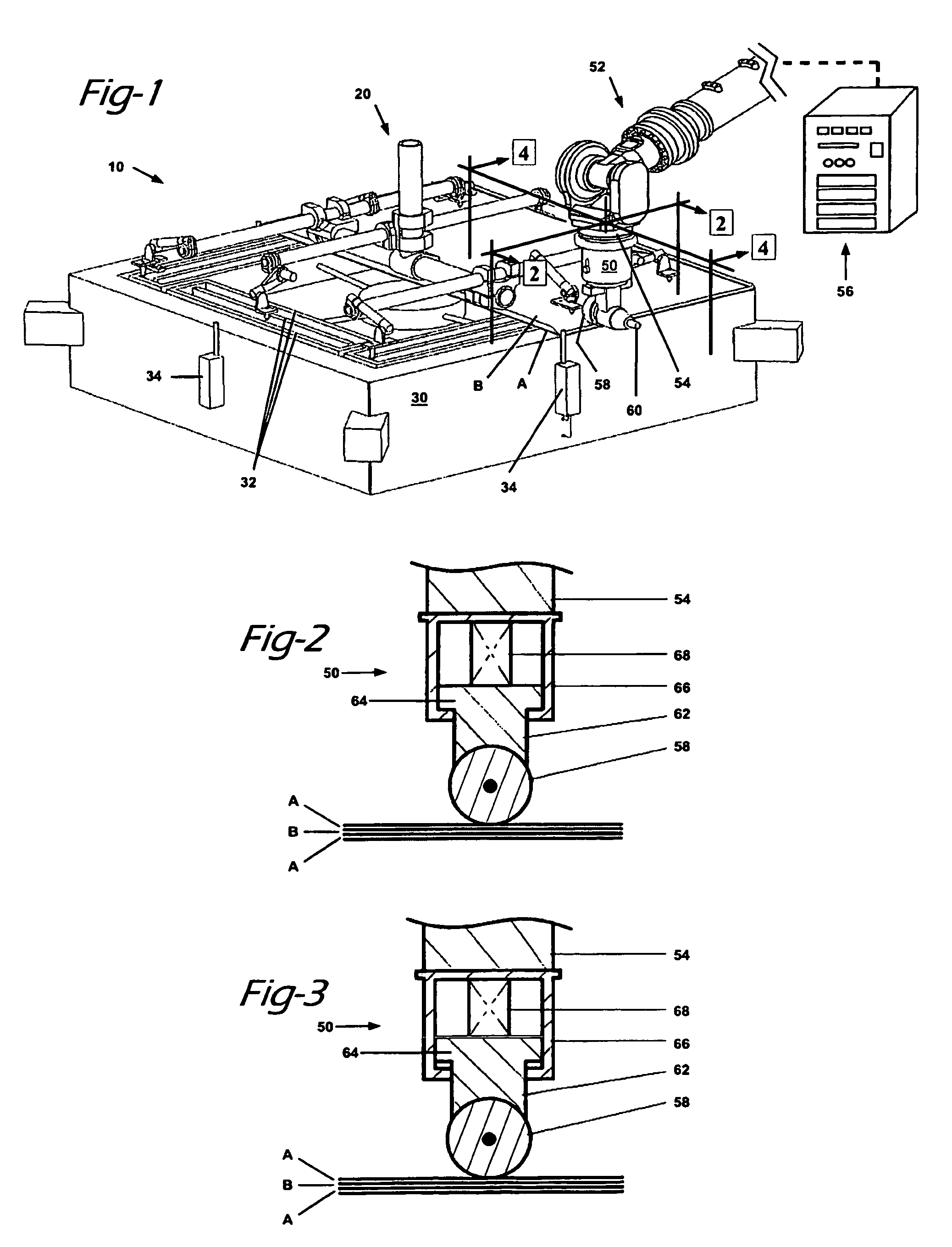
[0030]With reference first to FIG. 1, the preferred embodiment of a machine cell, generally referenced as 10, is illustrated in a perspective view. The machine cell 10 includes an upper gate 20 and a lower nest 30. It should be understood that the configuration of the machine cell 10 as illustrated is preferred, but is not to be interpreted as limiting as other configurations conceivable to those skilled in the art may also be suitable.

[0031]The machine cell 10 holds two portions of sheet material so that a joining process may be undertaken without the sheet material portions being caused to shift or otherwise move out of position. The two port...


PUM

PropertyMeasurementUnit
speedaaaaaaaaaa
speedsaaaaaaaaaa
sizeaaaaaaaaaa

Abstract

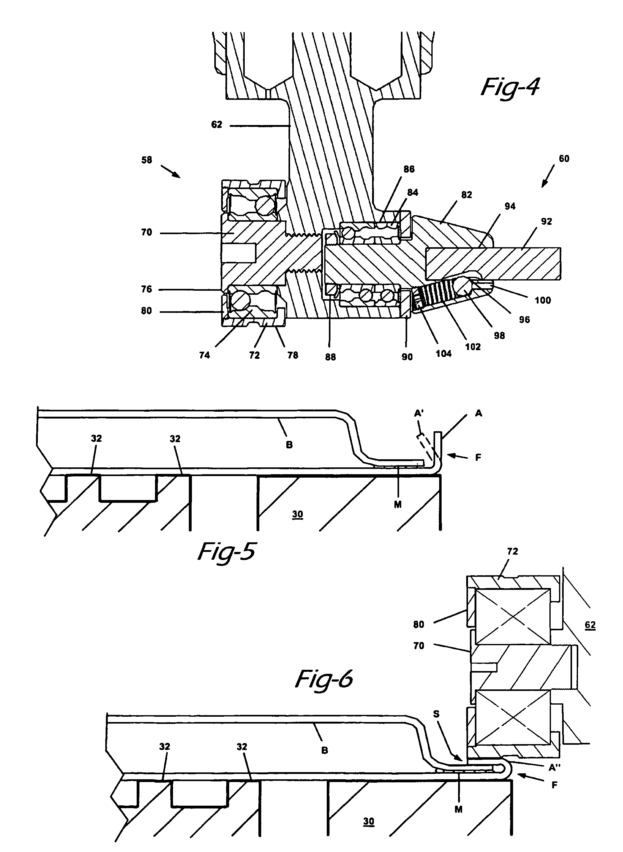
An apparatus and method for forming and joining a first sheet material (A) located in a nest (30) to a second sheet material (B) positioned on top of the first sheet material. The apparatus includes a positional pressure roller tool or positional pressure variance unit (50) for performing the forming and joining operations. The PPVU (50) may include both a main roller (58) and a touch-up roller (60). The PPVU (50) is operatively associated with a programmable positioning apparatus in the form of a robotic arm (52) and a machine cell (10) whereby the position of the robotic arm (52) relative to the nest (30) dictates the applied pressure at the interface between the roller (72) and the nest (30).

Description

FIELD OF THE INVENTION[0001]The present invention relates to systems for forming and joining a first sheet material to a second sheet material. More particularly, the present invention relates to a pressure-controlled roller tool and method of use in the forming and joining of sheet material.DESCRIPTION OF THE RELEVANT ART[0002]One of the earliest operations required in the history of automobile assembly was the joining of an inner panel to an outer panel to form any of a variety of body parts, including doors, engine hoods, fuel tank doors and trunk lids, all referred to as “swing panels” which encase the vehicle frame. Known machines for the forming and joining of sheet materials include the press-and-die set, the tabletop and the roller-forming tool, the latter being the most-recently introduced device.[0003]An unfortunate feature of forming and joining materials with the roller-forming tool is the difficulty in controlling the variable pressures required by the tool. A certain a...

Claims


Application Information

Patent Timeline
Patent Type & Authority Patents(United States)
IPC IPC(8): B21D39/02
CPCB21D39/021B21D39/023Y10T29/53791
Inventor CAMPIAN, JONATHON REO
Owner MODERN BODY ENG CORP
Learn More