Integrated stator-axle for in-wheel motor of an electric vehicle

a technology of electric vehicles and stators, applied in the direction of electric devices, magnetic circuit rotating parts, magnetic circuit shape/form/construction, etc., can solve the problems of increasing the probability of premature motor and system failure, and presenting additional challenges, so as to maximize the interaction with rotor elements and enhance the flux concentration

Inactive Publication Date: 2007-08-14
BLUWAV SYST LLC
View PDF19 Cites 24 Cited by
  • Summary
  • Abstract
  • Description
  • Claims
  • Application Information

AI Technical Summary

Benefits of technology

[0008]The present invention fulfills the above described needs, at least in part, by provision of an electrically powered vehicle having one or more wheels containing a motor rotor and a motor stator that is mounted on an integrated structure having a wheel axle portion and a motor stator mounting element portion. The structure is fabricated from a unitary non-ferromagnetic substance. The stator mounting element portion has a cylindrical configuration with its axis collinear with the axis of the axle. At least one ferromagnetic segment of the motor stator is joined directly to the stator mounting element portion. Preferably, the motor stator comprises a plurality of ferromagnetic core segments ferromagnetically isolated from each other and mounted on the stator mounting element portion of the integrated structure. Such isolation enhances flux concentration to maximize interaction with rotor elements.
[0010]A hollow central passage, extends along the axis of the axle portion and the stator mounting element portion. A plug in the passage prevents flow of air in a direct path along the entire passage. A plurality of cavities, provided with heat exchanger fins or other cooling surfaces, are contained within the stator mounting element portion. Each cavity forms an arc at a fixed radial distance from the axis and extends in a direction parallel to the axis from a first end to a second end. Channels at each end of each cavity extend in the radial direction from the respective cavity to an opening in the central passage. The plug in the central passage is located at a position intermediate the locations along the axis of the first and second ends of the cavities. Thus, incoming air from one end of the central passage is directed through the inlet channels to the first ends of the cavities, through the cavities and heat exchanger surfaces to the second ends of the cavities, through the outlet channels at the second ends and into the central passage near the exit. The wheel axle portion additionally contains one or more channels for providing wire access to the motor stator.

Problems solved by technology

Considerable manufacturing complexity is involved in providing the proper structural support for maintaining the motor stator and the stationary shaft separated and positioned in relation to the wheel axle.
Each of these detractors increases the probability of premature motor and system failure.
Provision of electrical connections to the stator elements and channeling of fluid to the stator for thermal management present additional challenges.

Method used


Image

  • Integrated stator-axle for in-wheel motor of an electric vehicle
  • Integrated stator-axle for in-wheel motor of an electric vehicle
  • Integrated stator-axle for in-wheel motor of an electric vehicle

Examples


Embodiment Construction

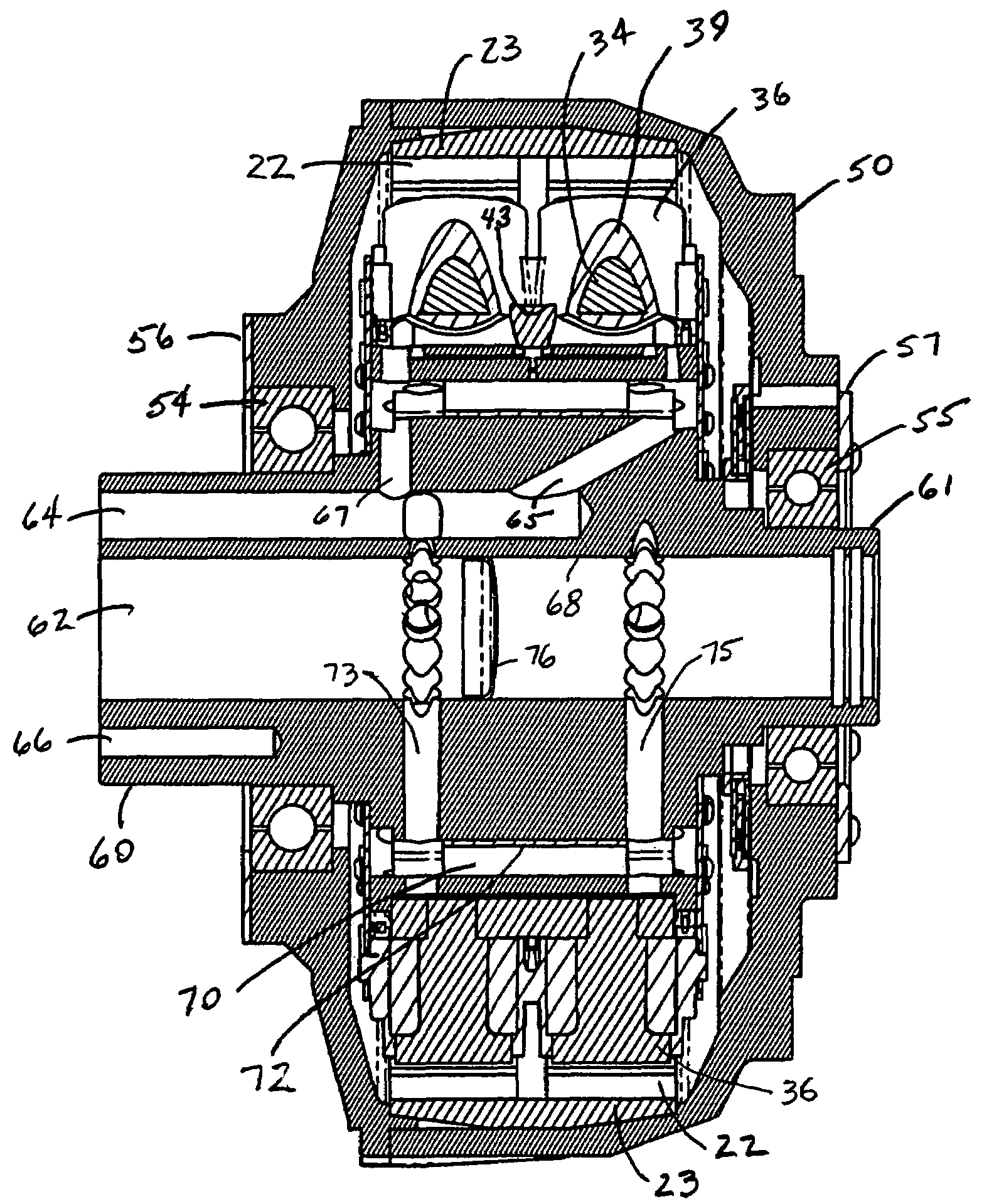
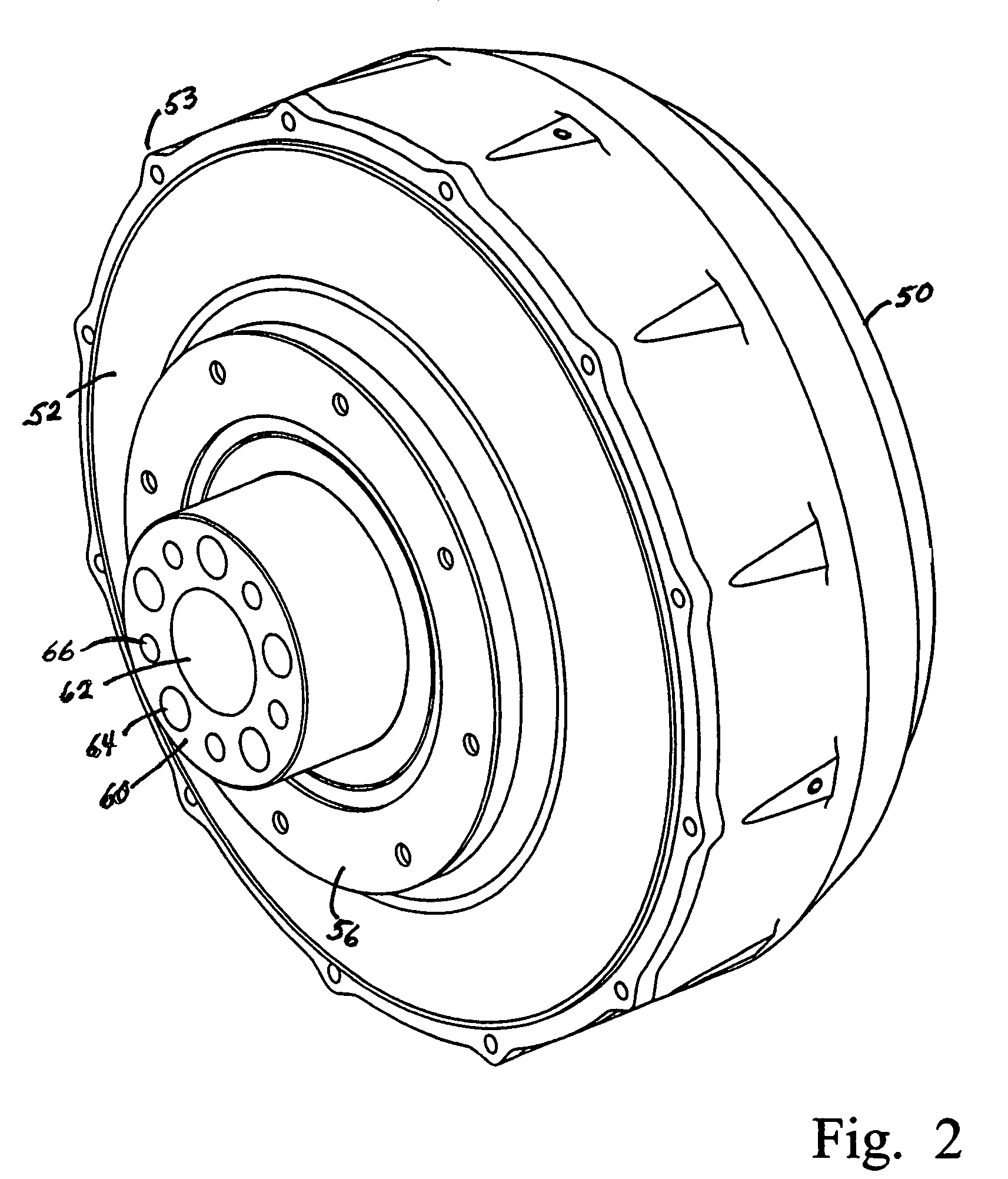
[0022]In the present invention, stator elements are directly mounted on an integrated structure that includes an axle portion and a stator element mounting portion. The rotor radially surrounds the stator and is separated therefrom by a radial air gap. FIG. 2 is a perspective view that illustrates a rotor housing 50 to which is attached rotor cover 52 at protrusions 53. A vehicle wheel can be mounted on and secured to the rotor housing. The rotor is journalled to the axle portion 60, which is an inner section of the integrated structure, through bearings that are retained within inner bearing retainer ring 56. As will be evident from other drawing figures, which are discussed below, the integrated structure includes an axle portion formed on each axial side of a stator mounting portion. Axle portion section 60 contains a hollow central passage 62, cable channels 64 and mounting holes 66, all of which are oriented generally parallel to the axis. Only central passage 62 extends throug...


PUM


Abstract

One or more wheels of an electrically powered vehicle contains a motor rotor and a motor stator that is mounted on an integrated structure having a motor stator mounting element portion and wheel axle portion on each side thereof. The structure is fabricated from a unitary non-ferromagnetic substance. A rotor housing is journalled to the axle portion on both sides of the motor stator mounting element via bearings. A wheel assembly is mounted on the rotor housing thereby to be driven by the rotor. Forced-air cooling is provided through a hollow central passage. A plug separates the passage into two distinct sections, the inlet and the outlet. A plurality of cavities, provided with heat exchanger surfaces, are contained within the stator mounting element portion. Channels at each end of each cavity extend in the radial direction into the central passage. Cooling air enters from one end of the central passage, is directed through the inlet channels, the cavities and outlet channels before exiting through the opposite end of the central passage. Additional channels provide wire access to the motor stator.

Description

RELATED APPLICATION[0001]This application is a divisional of U.S. application Ser. No. 10 / 706,277 filed on Nov. 13, 2003.FIELD OF THE INVENTION[0002]The present invention relates to electrically powered vehicles, more particularly to a vehicle wheel including a drive motor and an integrated motor mounting and wheel axle structure.BACKGROUND[0003]Development of efficient and versatile direct current motor drives has provided advantageous implementation in battery powered electric vehicles. A vehicle drive motor, with or without control circuitry therefor, can be incorporated in one or more wheels of a vehicle for direct provision of wheel traction. Such arrangements are exemplified in U.S. Pat. No. 6,617,746 to Maslov et al. and U.S. Pat. No. 6,492,756 to Maslov et al., both patents commonly assigned with the present invention and incorporated herein in their entirety.[0004]FIG. 1 is a partial three dimensional perspective diagram of the structure of the central portion of a vehicle ...

Claims


Application Information

Patent Timeline
Patent Type & Authority Patents(United States)
IPC IPC(8): H02K1/18B60K7/00H02K1/20H02K5/173H02K7/14H02K11/04H02K21/22
CPCB60K7/0007H02K7/14H02K21/222B60K2001/003B60K2007/0038B60K2007/0092Y02T10/641H02K11/0073H02K5/1732B60L2220/44B60L2220/50H02K11/33Y02T10/64
Inventor PERKINS, WILLIAM P.PALAZZOLO, JOSEPHPEYGHALEH, MANSOURBENSON, MARK A.
Owner BLUWAV SYST LLC
Why Eureka
Try Eureka