Stick lever units

a technology of levers and levers, applied in the direction of mechanical control devices, pulse techniques, coding, etc., can solve the problems of wiring conductors b>110/b> to break, unfavorable operator feeling, etc., and achieve the effect of convenient insertion work

Active Publication Date: 2007-08-14
FUTABA CORPORATION
View PDF8 Cites 4 Cited by
  • Summary
  • Abstract
  • Description
  • Claims
  • Application Information

AI Technical Summary

Benefits of technology

[0016]In the stick lever unit according to the present invention, the electrical wiring conductors from the second variable resistor can be derived out from the fixing member through the lead-out hole formed in one rotational shaft of the first rotational member journalled on the fixing member or through the lead-out hole formed on the other rotational shaft of the first rotational member linked to the first variable resistor. Hence, even when the first rotational member rotates by means of the stick operation, the movement of the electrical wiring conductors is small. This provides small resistance on manipulation and small uncomfortable feeling to the stick operator. Moreover, it becomes hard to damage and line break the electrical conductors. Deriving the wiring conductors from the fixing member can be realized through selecting at least one (or both, if necessary) of two rotational shafts of the first rotational member. This feature provides facilities for electrical connection to external devices. There is a lot of flexibility in device design.
[0017]In the stick lever unit according to the present invention, the electrical wiring conductors of the second variable resistor are derived out from the fixing member through the guide hole formed in the rotational shaft of the first rotational member to which the second variable resistor is attached. Hence, even when the first rotational member rotates by the stick operation, the movement of the electrical wiring conductors is small. This provides a small sense of resistance and minimizes any uncomfortable feeling on operation to the stick operator. Moreover, it reduces the likelihood that the electrical conductors are damaged and line-broken.
[0018]According to the stick lever unit according to the present invention, in the first variable resistor, the rotational operation section varying the resistance value has a rotational body having a through hole. The rotational body rotates to the fixing member by means of only the rotational shaft mounted on the first rotational member. The electrical conductors of the second variable resistor are derived from the fixing member through the guide hole formed on the rotational shaft of the first rotational member and through the through hole in the first variable resistor. This feature improves the stick operability to rotate the first rotational member. Thus, the effect of the stick lever unit according to the present invention can be obtained certainly.
[0019]According to the stick lever unit according to the present invention, the structure fabricable in a simple procedure can realize the effect of the stick lever unit. That is, the stick lever unit can be fabricated in the steps of first mounting the first rotational member to the fixing member via the rotational shaft, then inserting the rotational body of the first rotational member into the end of one rotational shaft protruded outward from the fixing member, and fixing the first variable resistor to the outer surface of the fixing member.
[0021]In the stick lever unit according to the present invention, the aperture diameter of the guide hole decreases gradually toward the lead-out hole and the diameter of the guide hole, acting as the exit for the electrical wiring conductors, increases in the exit direction. Hence, when the electrical conductors are inserted into the fixing member from the guide hole through the lead-out hole opening at the end of the rotational shaft of the first rotational member, the insertion work is easily performed.

Problems solved by technology

This works as a resistance when the stick 106 is operated which causes an uncomfortable feeling to the operator.
This repeated deformation over a long period of time may cause the wiring conductors 110 to break.

Method used


Image

  • Stick lever units
  • Stick lever units
  • Stick lever units

Examples


Embodiment Construction

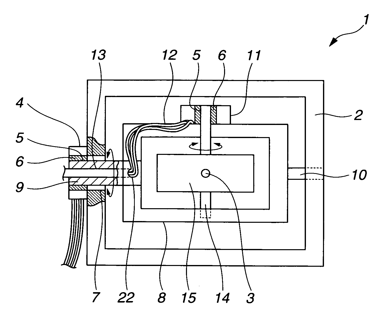
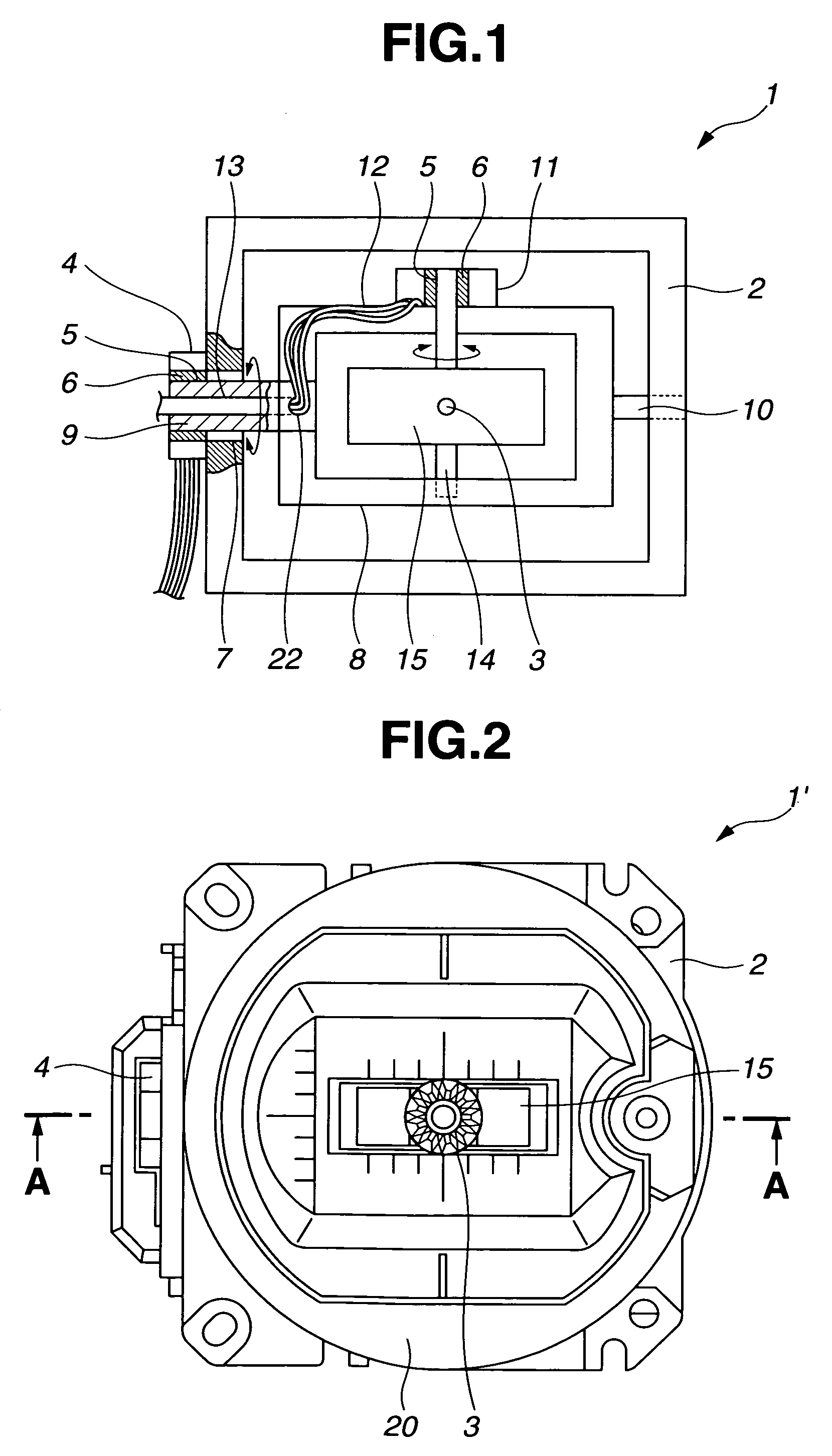
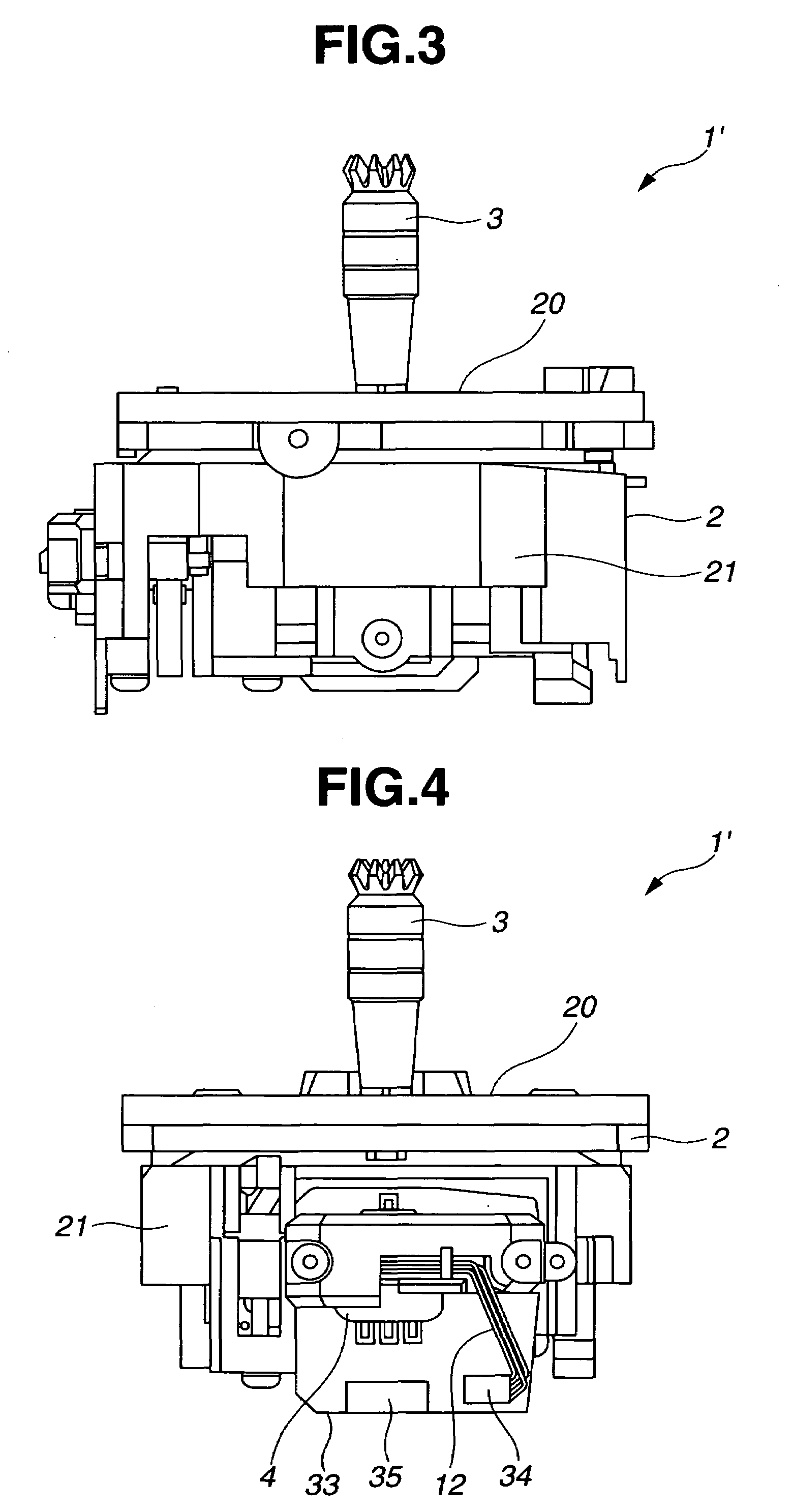
[0035]The best mode for embodying the present invention will be described below by referring to FIGS. 1 to 12. The basic structure of a stick lever unit according to the present invention will be explained below by referring to FIG. 1.

[0036]The stick lever unit 1 of the present embodiment includes as a main body a fixing member 2 fixed to the housing of a radio-controlled transmitter. The fixing member 2 is a frame member, in a nearly rectangular shape, having a space in which the rotational mechanism of the stick 3 is assembled. A first variable resistor 4 is mounted on the outer side of the side wall of the fixing member 2. The first variable resistor 4 is a rotational-type variable resistor that includes a rotational body 6 with a through hole 5, as a rotational operation section varying the resistance value. When the shaft, which is connected to the rotational body 6 through the through hole 5, is rotated, the resistance value changes. The opening 7 is formed in one side wall of...


PUM


Abstract

A stick lever unit is provided that is capable of eliminating uncomfortable feeling during manipulation of the stick, as well as, minimizing breaking of a wiring conductor of the variable resistor. The stick lever unit includes a fixing member, a first variable resistor attached to the fixing member, a first rotational member rotatably journalled to the fixing member for rotationally controlling the first variable resistor, a second variable resistor attached to the first rotational member, and a second rotational member having a stick lever and being rotationally journalled to the first rotational member to rotationally control the second variable resistor. The wiring conductors of the second variable resistor are derived out from the lead-out hole in the rotational shaft of the first rotational member, which is attached to the second variable resistor.

Description

CROSS REFERENCES TO RELATED APPLICATIONS[0001]This application claims the priority benefit of Japanese Patent Application No. 2004-287931 filed on Sep. 30, 2004 and Japanese Patent Application No. 2004-287932 filed on Sep. 30, 2004.STATEMENT REGARDING FEDERALLY SPONSORED RESEARCH[0002]Not Applicable.BACKGROUND OF THE INVENTION[0003]The present invention relates to stick lever units, which are capable of creating control signals for maneuvering of models, control of industrial machines, manipulation of game consoles, and the like.[0004]Generally, stick lever units for creating control signals are attached to radio controlled transmitters for maneuvering models, respectively. The basic structure of a conventional stick lever unit will be explained below by referring to the schematic diagram of FIG. 12. A first variable resistor 101 is attached to the outer side of a frame fixing member 100, which is attached on the housing of a radio-controlled transmitter. A first rotational member 1...

Claims


Application Information

Patent Timeline
Patent Type & Authority Patents(United States)
IPC IPC(8): H01C10/16
CPCH01C3/16G05G2009/04748A63F13/24
Inventor ARAI, MASAHIROTOKITA, MASASHIISONO, TAKAHIRO
Owner FUTABA CORPORATION
Why Eureka
Try Eureka