

Load sharing in SS7 networks
- Summary
- Abstract
- Description
- Claims
- Application Information
AI Technical Summary
Benefits of technology
Problems solved by technology
Method used
Image

Examples
Embodiment Construction
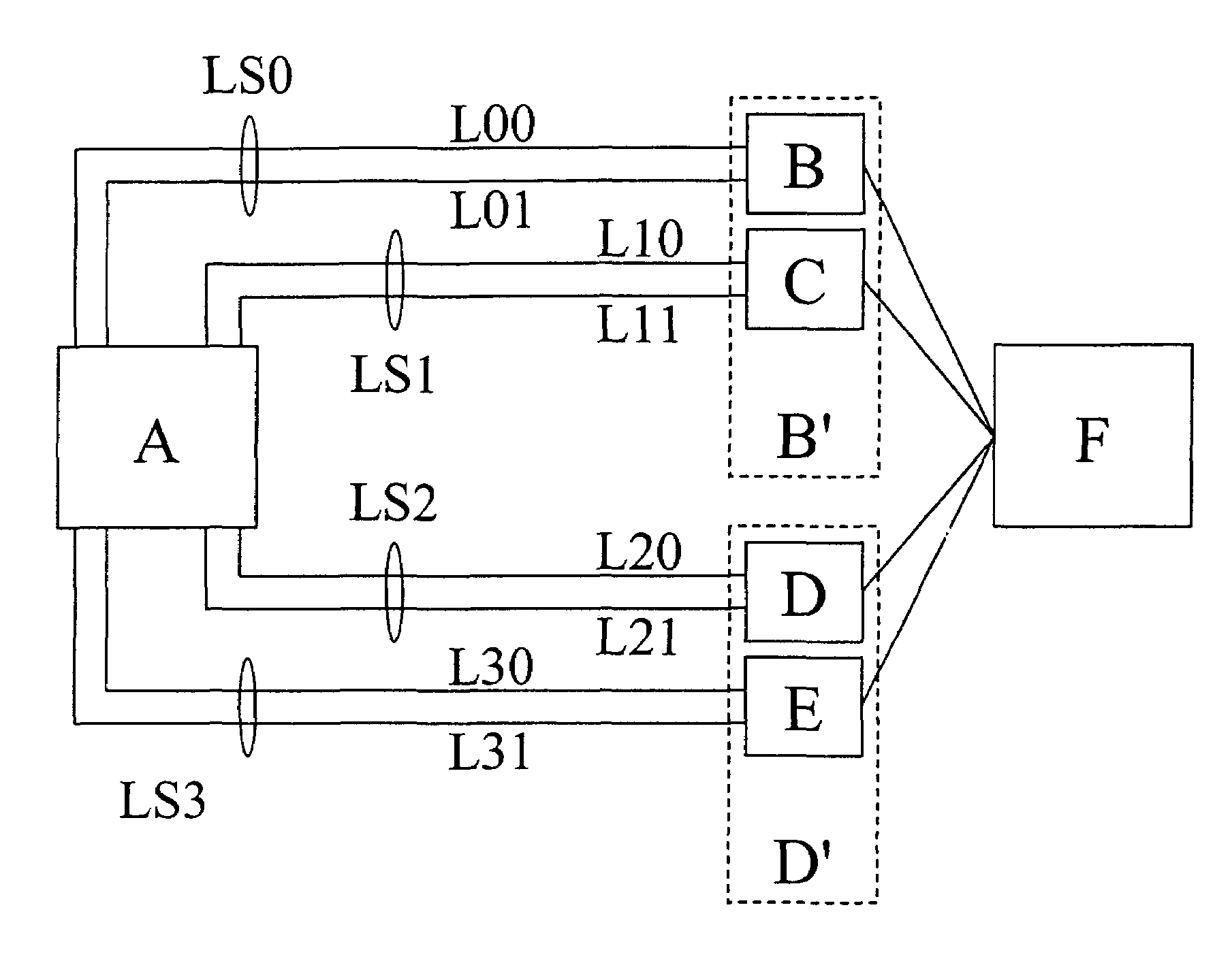
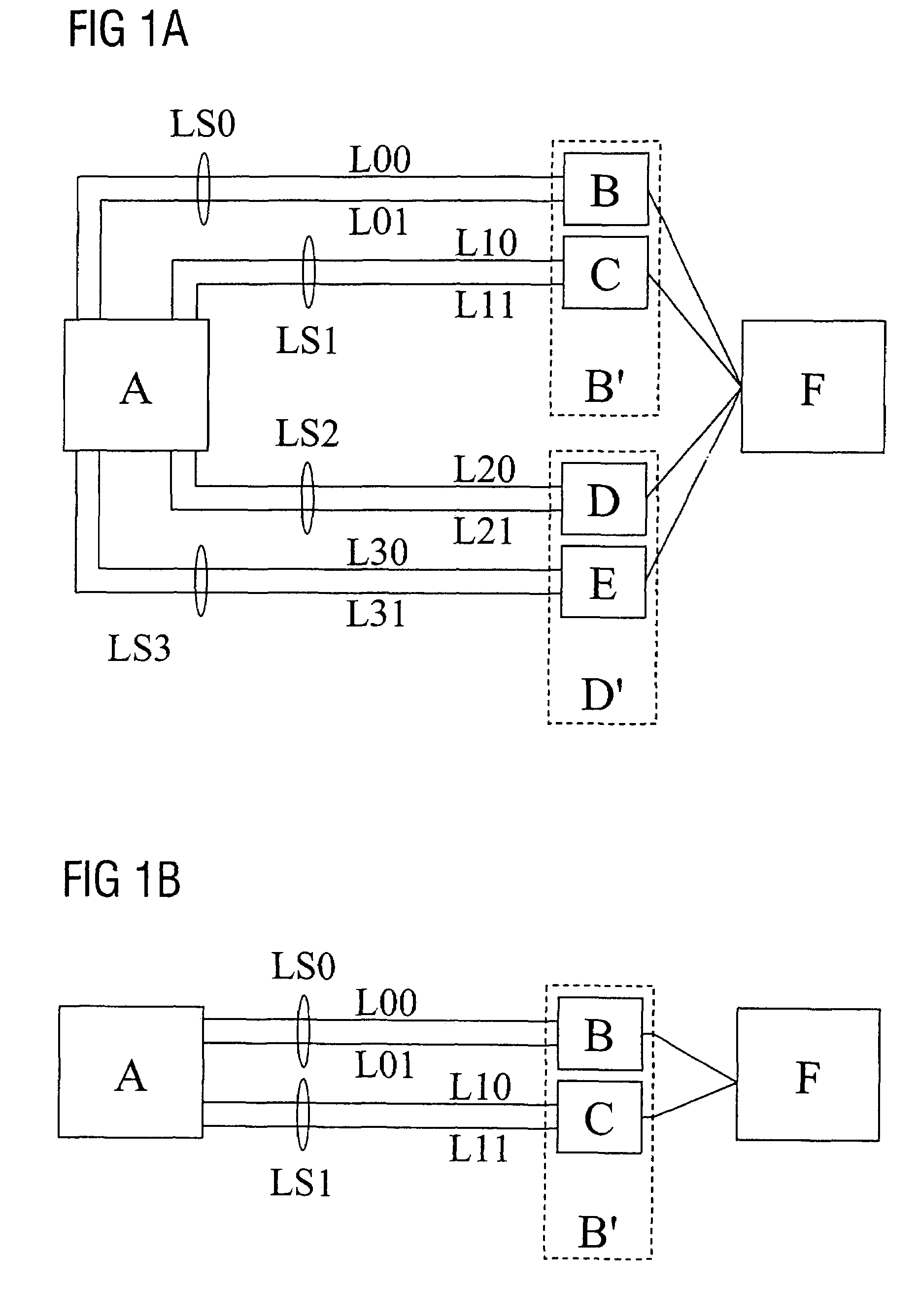
[0025]FIG. 1 shows two typical network arrangements. In FIG. 1A, a first signaling point SP A is connected to a second signaling point F by means of four further signaling points SP B, SP C, SP D, SP E. Four link sets LS0, LS1, LS2, LS3 are used to establish the connection between SP A and the further signaling points SP B . . . E. In this arrangement, each of the link sets comprises two links L00, L01 and L10, L11 and L20, L21 and L30, L31. The connections between SP F and the further signaling points SP B . . . E can be implemented as desired.
[0026]The arrangement in FIG. 1B corresponds to the arrangement from FIG. 1A, albeit with the omission of SP D and SP E as well as LS2 and LS3 and their assigned links L20, L21 and L30, L31.
[0027]The cited SP A and SP F can be signaling end points SEP or signaling transfer points STP. This is of no significance for the present invention, however. With regard to the communication between SP A and SP F, the further signaling points SP B, SP C, ...
PUM
 Abstract
Description
Claims
Application Information