Method for determining a refuse filling level

A grinder and material level technology, which is applied to the material level field of the drum, can solve the problem of being unsuitable for the grinder to rotate, and achieve the effect of low implementation cost.

Inactive Publication Date: 2009-08-05
SIEMENS AG
View PDF0 Cites 11 Cited by
  • Summary
  • Abstract
  • Description
  • Claims
  • Application Information

AI Technical Summary

Problems solved by technology

[0005] Conventional methods for level detection such as the rotary vane, pendulum and vibration measurement methods offered by the company Mollet Füllstandstechnik GmbH on the Internet http: / / www.mollet-gmbh.de / Suitable for stationary storage containers, but not for rotating and loaded drums of grinders

Method used


Image

  • Method for determining a refuse filling level
  • Method for determining a refuse filling level
  • Method for determining a refuse filling level

Examples


Embodiment Construction

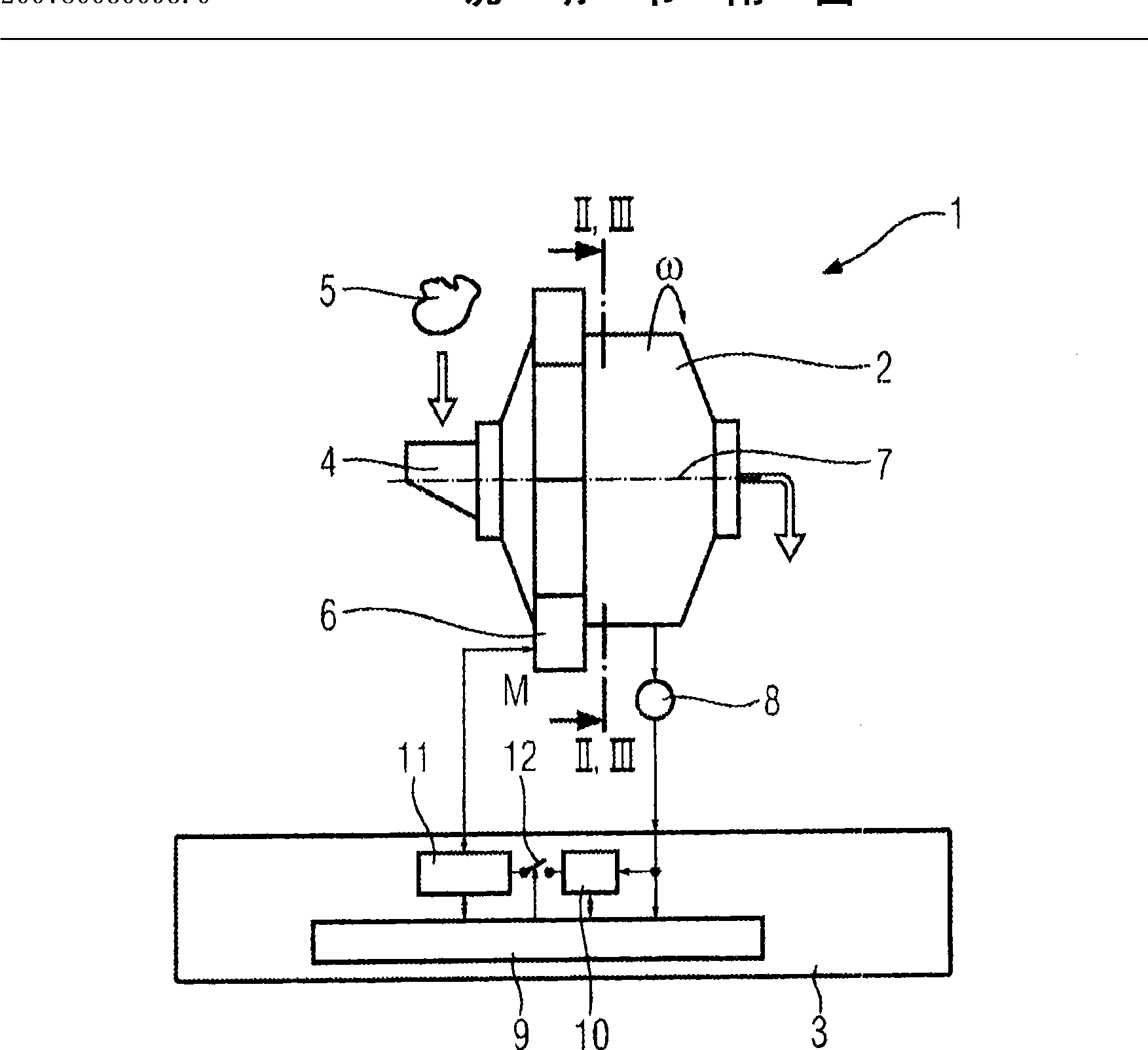
[0040] figure 1 An exemplary embodiment of a grinder 1 with a drum 2 and a control and regulation unit 3 is shown schematically. The attritor 1 is an ore grinding machine configured as a ball mill or as a SAG attritor. The drum 2 is connected to a feed shaft 4 by means of which ore material 5 to be ground reaches the interior of the drum 2 . For comminuting the ore material 5 , the loaded drum 2 can be driven in rotation about an axis of rotation 7 by means of a drive 6 , which is designed in the exemplary embodiment as a gearless electric motor.

[0041] A rotation speed sensor 8 for detecting the rotation speed n of the drum 2 is arranged on the drum 2 . The rotational speed sensor 8 is connected to the control and regulation unit 3 . The control and regulation unit 3 includes in particular at least one central processing unit 9 , for example in the form of a microcomputer, microprocessor or microcontroller module, a rotational speed regulator 10 connected to the rotation...


PUM


Abstract

The method is used to determine the filling level of a loaded refuse container (2). The container (2) has a drive torque (M) applied to it by means of a drive (6), and causes it to rotate (Omega). The drive torque (M) on the drive (6) is set by means of a predeterminable drive test sequence. A time/rotation speed profile of a rotation speed of the container (2) which results from the drive test sequence is recorded, and is analyzed. The filling level is determined on the basis of the results of the analysis. The method produces up to date, accurate information, determined during the refuse operation, about the filling level of the container (2).

Description

technical field [0001] The invention relates to a method for detecting the filling level of a loaded drum of a grinder. Background technique [0002] The grinder can be, for example, a ball mill or also a SAG (semiautogenously grinding) grinder designed for grinding coarse-grained materials such as ores or cement. Comminution takes place in the drum of such a grinder, and the current filling level in the drum is usually not known. This means that the filling level depends on many parameters. Examples of these parameters are the exact degree of grinding, the proportion of steel balls added to the drum to support the grinding process, the degree of wear of these balls and the solids fraction of the suspension currently present in the drum. Most of these parameters change during the operation of the grinder. Its current value is as unknown as the value of the fill level itself. [0003] It is therefore advantageous to know the current filling level exactly to a certain exte...

Claims


Application Information

Patent Timeline
Patent Type & Authority Applications(China)
IPC IPC(8): B02C17/18B02C25/00
CPCB02C17/1805B02C25/00
Inventor N·贝克H·-U·洛弗勒S·斯米茨K·蒂希勒
Owner SIEMENS AG
Why Eureka
Try Eureka