Production of radio frequency ID tags

a radio frequency identification and tag technology, applied in the direction of noise figure or signal-to-noise ratio measurement, instruments, semiconductor/solid-state device testing/measurement, etc., can solve the problem of requiring a fairly expensive process with narrow tolerances for the initial tuning, and the most fine tuning of semiconductor devices cannot make adjustments over a wide range of ranges

Inactive Publication Date: 2007-08-14
TAGENT
View PDF6 Cites 29 Cited by
  • Summary
  • Abstract
  • Description
  • Claims
  • Application Information

AI Technical Summary

Benefits of technology

[0010]Other aspects of the invention are testing of transmit response, signal strength, and other performance issues at the time of application of the tags to products or containers, rather than during manufacturing; burning a value in the RF ID chip during manufacture, the value being randomly selected and then applied to the chip to impose a random time delay for tag response (rather than having a random generator on the chip itself); structural testing of a large number of tags on a wafer using on-wafer interconnects and a special onboard sequencer test die; and production of the tag so as to be tunable to different frequency ranges, such tuning to be done either at subsequent testing or during tag application, to accommodate different jurisdictional frequency requirements. All of these production and testing features add to economy of producing the tag and reliability of the tags in service.

Problems solved by technology

This typically occurs while the dice are still on the wafer and also after each die has been cut from the wafer and assembled, and it is a costly procedure.
To eliminate any high variation in the manufactured devices, a fairly expensive process with narrow tolerances is required for the initial tuning.
Most fine tuning of semiconductor devices cannot make adjustments over a wide enough range to overcome the initial production offset, unless ATE type pre-tuning has been performed.
In addition, even within a single jurisdiction, different frequencies are often needed for different applications, within the same facility, for reasons relating to interference and false readings for different products or applications.

Method used


Image

  • Production of radio frequency ID tags
  • Production of radio frequency ID tags
  • Production of radio frequency ID tags

Examples


Embodiment Construction

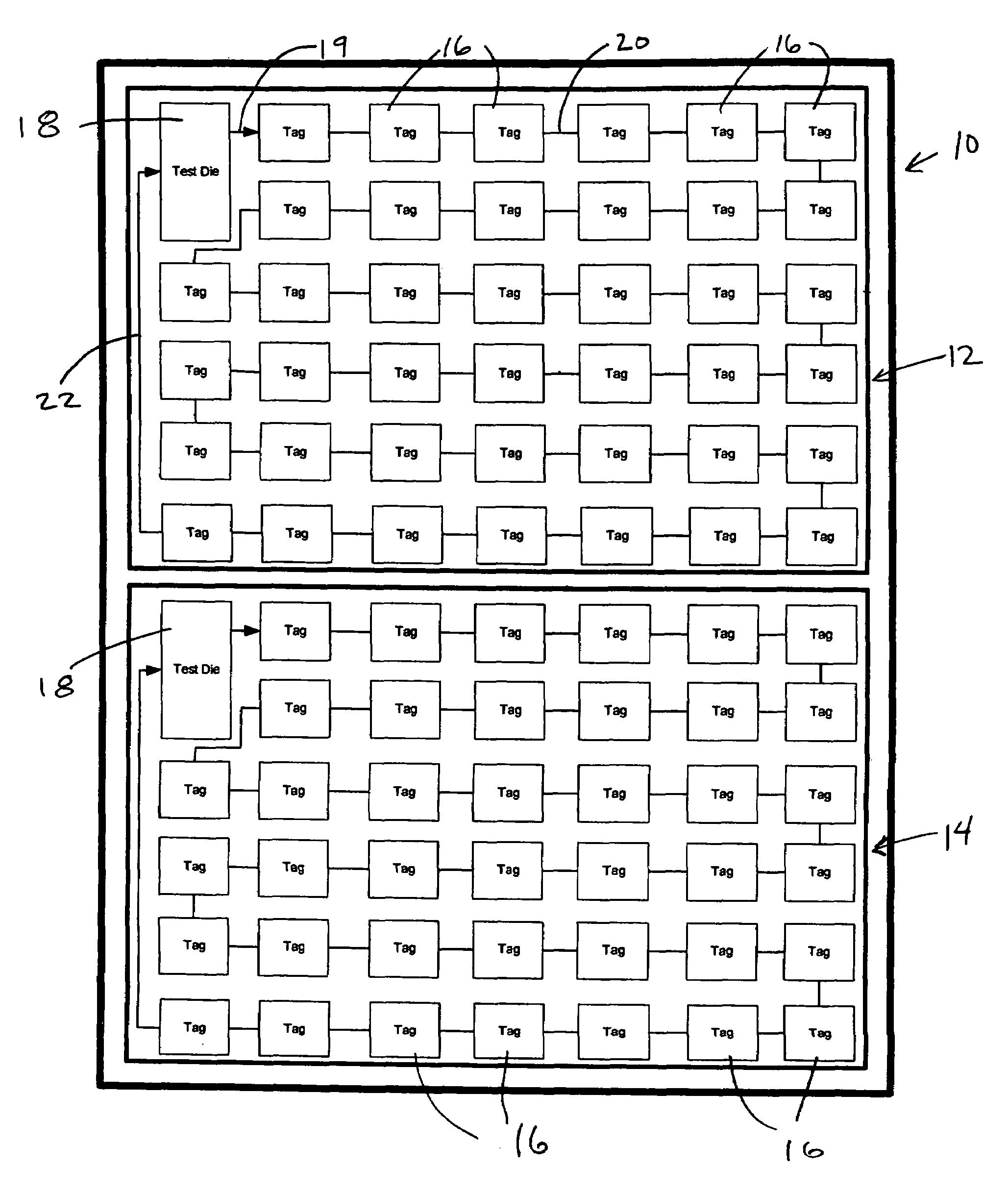
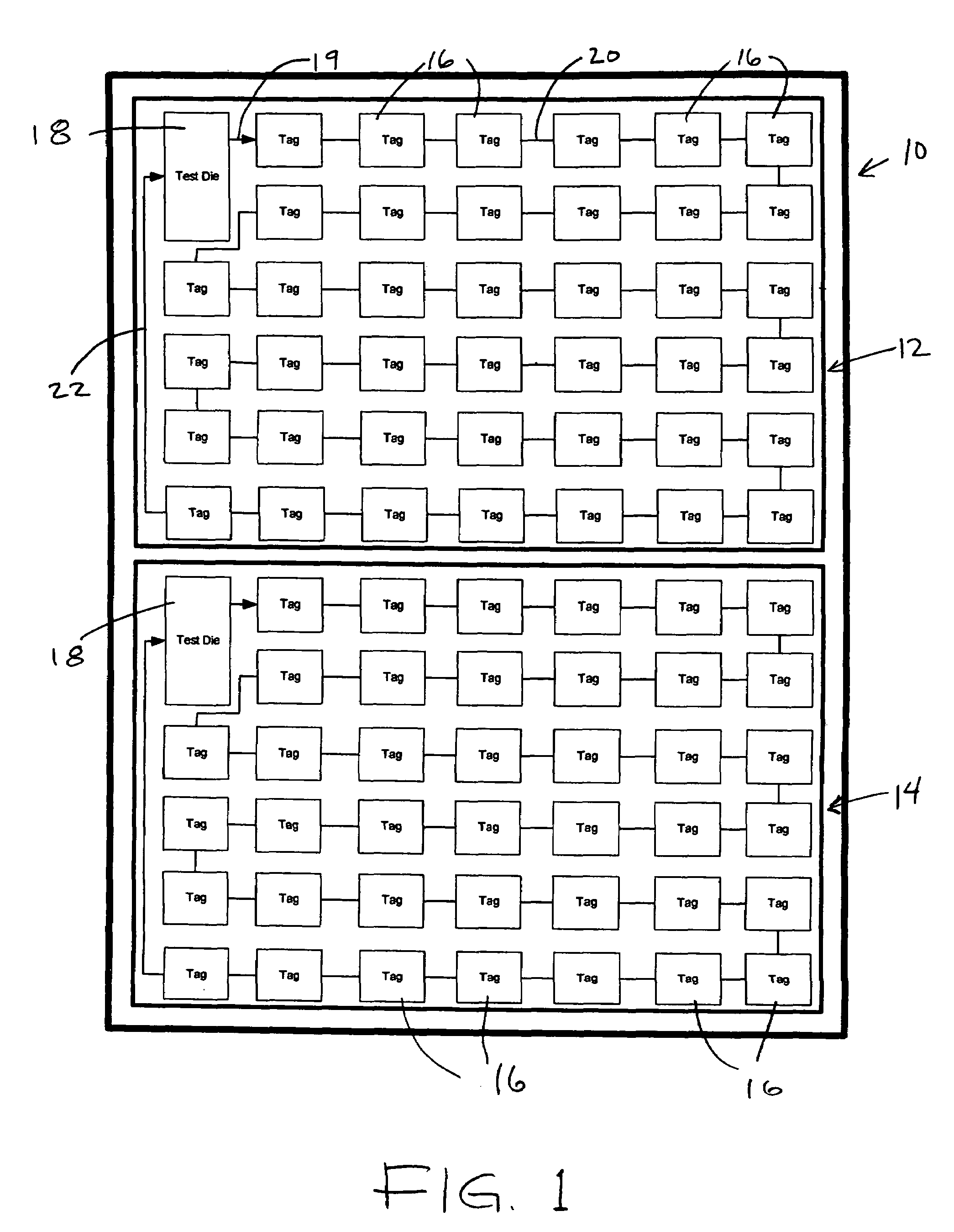
[0017]FIG. 1 shows the reticle field of a semiconductor wafer 10 in the manufacture of RF ID tags, in accordance with one aspect of the invention. In each of two sections 12 and 14 of the wafer, a multiplicity of tag dice 16 are connected in series to a test die 18 for that section. The number of tag dice will be dependent on the size of the tags 16 and the test die 18. The interconnection of all tag dice to the test die in the reticile field enables a tester to make contact only with the test die 18 in order to test all interconnected tag dice within that section of the wafer, without requiring that a probe make contacts with each individual tag dice 16. As indicated, a series of conductors 19 and 20, respectively (each of which may be a bus), connect the test die 18 to the first tag die 16 and the tags serially one to the next, so that through the tags, the test die 18 can connect to each one of the tag dice serially. All tag dice, and the test die 18, can be connected while on th...


PUM


Abstract

A radio frequency ID tag, very small in size and with an onboard antenna, is manufactured, tested and applied cost-efficiently. The transmit frequency for the tag is set during manufacture approximately, within a selected range, in a gross tuning step. A second tuning step fine tunes each tag by RF communication to set values of capacitance, resistance, etc., and this can be at the point of application of the tags. Other aspects include burning a randomly-selected value in the RF ID chip during manufacture to impose a random time delay for tag response (rather than having a random generator on the chip itself); structural testing of a large number of tags on a wafer using on-wafer interconnects and a special onboard sequencer test die; and production of the tag so as to be tunable to different frequency ranges.

Description

BACKGROUND OF THE INVENTION[0001]This invention concerns radio frequency identification tags to be used as identifiers and for counting and inventorying articles and containers of articles. In particular, the invention concerns a miniature RF ID tag generally of the type disclosed in U.S. Pat. No. 6,480,699, which is incorporated herein by reference.[0002]Radio frequency ID tags have been described in various forms, and designed for various purposes. The type of ID tag to which this invention is concerned essentially comprises an integrated circuit with an antenna onboard the chip, and with an energy store which will capture a portion of the RF energy from an interrogator unit, store that energy and use it to power a responding signal transmitted from the tag, as in U.S. Pat. No. 6,480,699.[0003]Currently, in the manufacture of semiconductor devices (for a variety of different purposes, not only ID tags) dice are tested by connecting each die individually with a tester. This typical...

Claims


Application Information

Patent Timeline
Patent Type & Authority Patents(United States)
IPC IPC(8): H04B1/59H04Q5/22
CPCG06K7/10059G06K19/0723G06K19/0726
Inventor BOLANDER, JARIE G.WUNDERLICH, FORRESTJARVIS, NEILLEE, CHRISTOPHER J.BARON, BERNARDLOVOI, PAUL A.
Owner TAGENT
Why Eureka
Try Eureka