
Content addressable memory capable of changing priority in priority encoder

a technology of priority encoder and content addressable memory, which is applied in the field of priority encoder, can solve problems such as the complication of managing the data stored in the cam, and achieve the effect of facilitating the management of stored data items and search results

Inactive Publication Date: 2007-08-14
KAWASAKI MICROELECTRONICS
View PDF3 Cites 2 Cited by
  • Summary
  • Abstract
  • Description
  • Claims
  • Application Information

AI Technical Summary

Benefits of technology

[0015]In view of the above circumstances, it is an object of the present invention to provide a CAM in which the management of stored data items and search results is facilitated, and in which order of priority in a priority encoder can be changed while suppressing a decrease in throughput.

Problems solved by technology

However, these methods have a problem of complication in managing the data stored in the CAM and the results of searching output from the CAM.

Method used


Image

  • Content addressable memory capable of changing priority in priority encoder
  • Content addressable memory capable of changing priority in priority encoder
  • Content addressable memory capable of changing priority in priority encoder

Examples


first embodiment

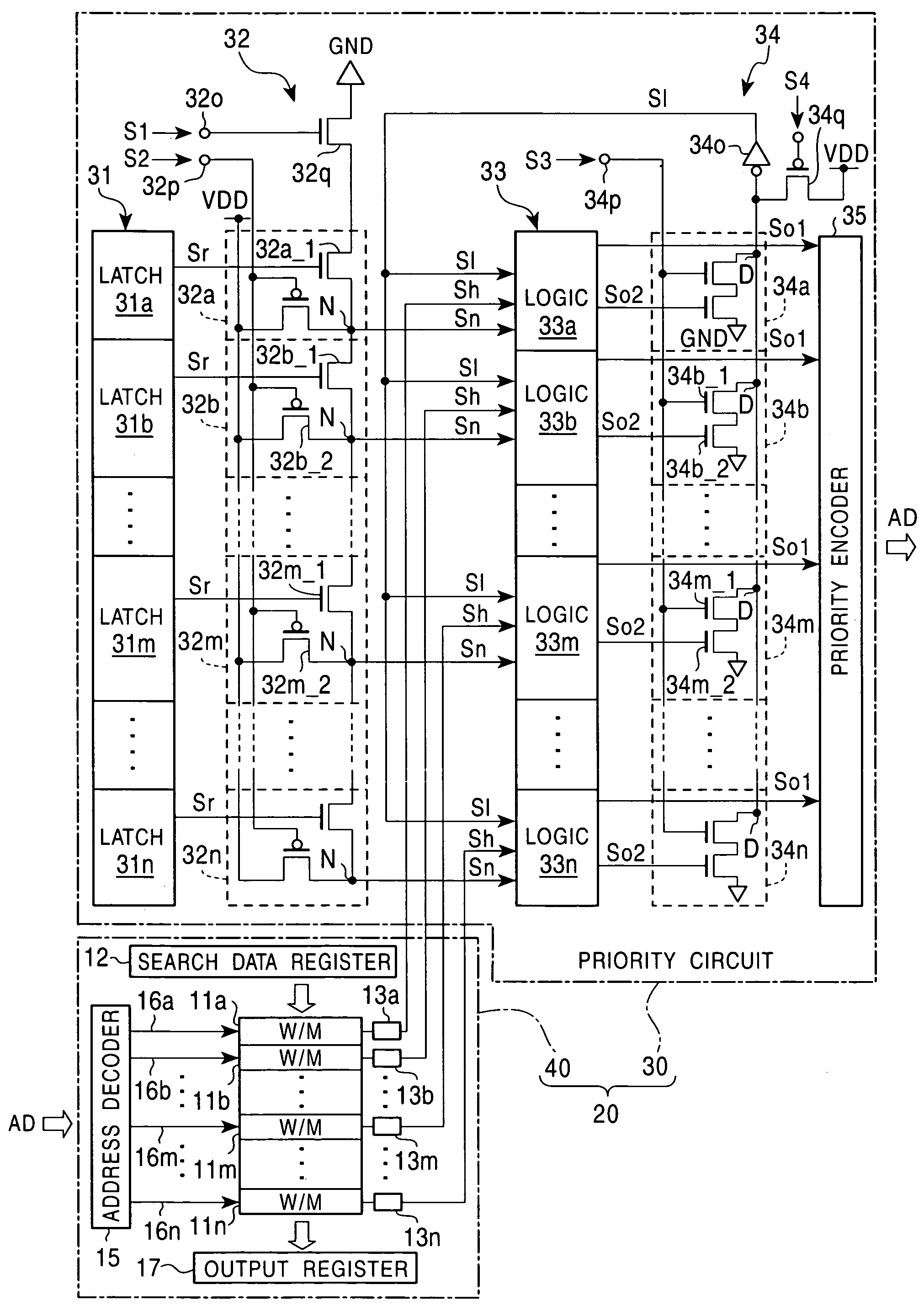
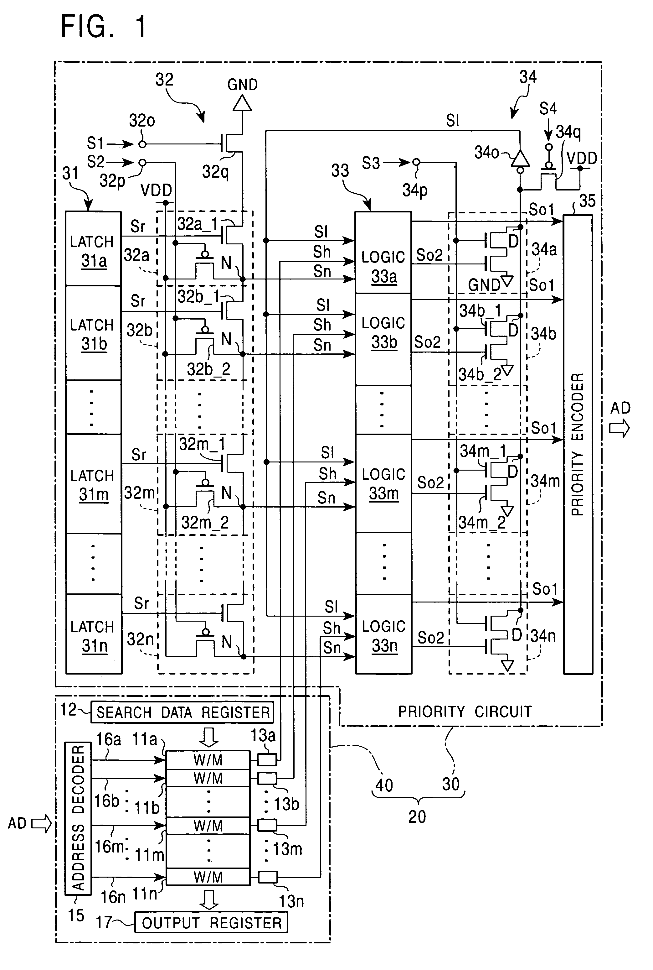
[0034]FIG. 1 is a block diagram showing a CAM 20 according to the present invention.

[0035]A portion of the CAM 20 which includes word memories 11a, 11b, . . . , 11n, a search data register 12, flag registers 13a, 13b, . . . , 13n, an address decoder 15, word memory lines 16a, 16b, . . . , 16n, and an output register 17 is identical in configuration and operation to the above portion of the conventional CAM 10 shown in FIG. 13. Accordingly, the components in the portion of the CAM 20 are denoted by identical reference numerals, and a detailed description of each component is omitted. The present invention is characterized by a priority circuit 30.

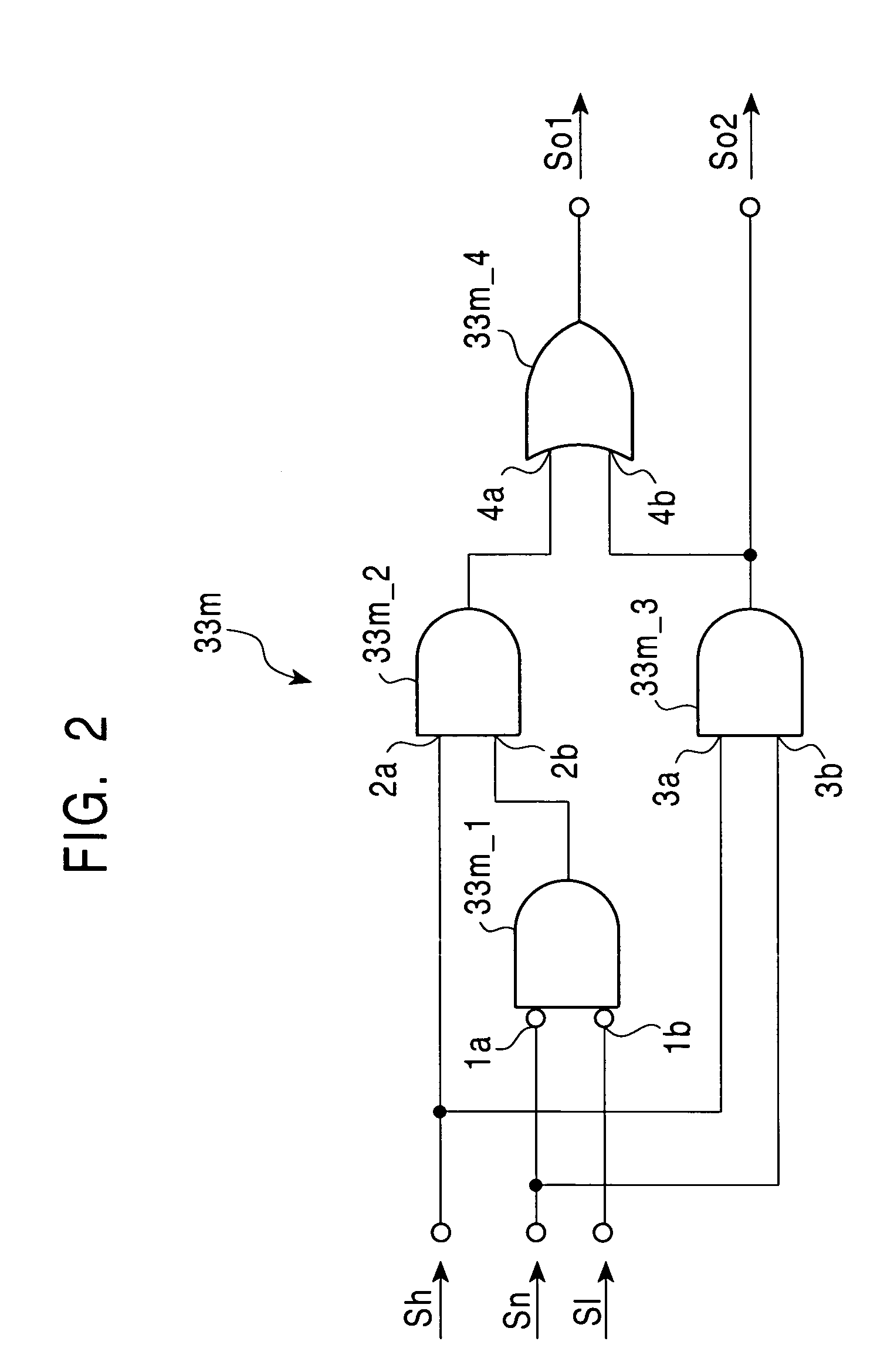
[0036]The priority circuit 30 includes a first prior word-memory setting unit (hereinafter referred to as “the first prior W / M setting section”) 31, a division circuit 32, an upper-side mask circuit 33, a detection circuit 34, and a priority encoder 35. In the first embodiment, for a plurality of word memories, fixed priority levels in the p...

second embodiment

[0077]Next, the present invention is described below.

[0078]FIG. 4 is a block diagram showing a CAM 60 according to a second embodiment of the present invention.

[0079]In FIG. 4, components identical to those described with reference to FIG. 1 are denoted by identical reference numerals. Accordingly, a detailed description thereof is omitted.

[0080]The CAM 60 consists of a priority circuit 50 and a memory portion 40. The priority circuit 50 includes a first prior word-memory setting section 51, a first division circuit 52, a last prior word-memory setting section 53, a last division circuit 54, a mode signal generating circuit 55, a mask circuit 56, a detection circuit 34, and a priority encoder 35.

[0081]The first prior word-memory setting section 51 sets, from among a plurality of word memories in the memory portion 40, a word memory whose address is to be output prior to the addresses of the other word memories. The designated word memory is hereinafter referred to as the first prior...


PUM


Abstract

A content addressable memory includes a plurality of word memories which respectively have assigned addresses, and each outputs a match / mismatch signal representing storage or no storage of a data item matching search data in a search mode, a priority encoder which output addresses of word memories which output the match signals in the search mode in predetermined fixed priority order, a first prior word-memory setting section for setting a first prior word memory, and a priority changing part which masks the match signals output from upper-positional word memories of the word memories, which correspond to word memories having upper positions compared with the first prior word memory in the fixed priority order in the priority encoder, and transmits signals representing that the word memories having the upper positions output no match signals to the priority encoder.

Description

BACKGROUND OF THE INVENTION[0001]1. Field of the Invention[0002]The present invention relates to a content addressable memory (hereinafter referred to as a “CAM”), and in particular, to a priority encoder for use in a CAM.[0003]2. Description of the Related Art[0004]FIG. 13 is a circuit block diagram showing a CAM 10 as an example of a conventional CAM.[0005]The CAM 10 shown in FIG. 13 includes a plurality of word memories 11a, 11b, . . . , 11n storing a bit pattern for one word. The CAM 10 includes a search data register 12 for latching one word of input search data. All or predetermined part of the bit pattern of search data latched by the register 12 is compared with the bit pattern of a portion of data stored in each word memory which corresponds to the all or a predetermined part of the bit pattern. This detects matching / mismatching between the two. Match / mismatch signals (also called “hit signals”) representing matching or mismatching are output from the word memories 11a to 1...

Claims


Application Information

Patent Timeline
Patent Type & Authority Patents(United States)
IPC IPC(8): G06F13/00G11C15/00
CPCG11C15/00
Inventor KANAZAWA, NAOKI
Owner KAWASAKI MICROELECTRONICS
Learn More