Integrated active ultrasonic probe

an active, ultrasonic probe technology, applied in the field of ultrasonic probes, can solve the problems of difficult maneuverability, large volume of probe cable between phased array probe and processing station, and inability to fully integrate the probe, so as to facilitate the analysis and visualization of ultrasonic echo data and improve the signal-to-noise ratio.

Active Publication Date: 2016-01-26
BAKER HUGHES INC
View PDF9 Cites 4 Cited by
  • Summary
  • Abstract
  • Description
  • Claims
  • Application Information

AI Technical Summary

Benefits of technology

[0006]One aspect of the invention is an integrated active ultrasonic probe and a processing system operable with the integrated active ultrasonic probe. The integrated active ultrasonic probe includes specialized hardware and processing components required for generating ultrasonic test data which can be transmitted over a standard digital interface to a connected processing system. By moving specialized hardware and processing into the integrated active ultrasonic probe, the use of a generic processing system, or processing unit, such as a PC / workstation, laptop, or tablet, to analyze and visualize the ultrasonic echo data is facilitated. This relieves the requirement for specialized hardware and processing in the processing station. The new design is integrated into a small volume that fits into the probe housing that can be maneuvered within test objects. Signal-to-noise ratio is improved because shorter wires connect processing electronics directly to the ultrasonic transducers. The ultrasonic transducers and the processing of data generated thereby are part of the integrated active ultrasonic probe and heavy cables for housing significant data transmission lines are not required.
[0007]The ultrasonic probe includes ultrasonic transducers and processing electronics to control emission of ultrasonic energy and to process and digitize returned echo data. Processed echo data can then be transmitted over a standard digital interface. Advantages that may be realized in the practice of some disclosed embodiments of the integrated active ultrasonic probe is improved signal-to-noise and compatibility with various processing systems.

Problems solved by technology

The length of the cables tends to create added noise in the returning echo data.
For phased array ultrasonic probes containing such a large number of transducers, or more, the probe cable between the phased array probe and the processing station can be quite dense and is difficult to maneuver.

Method used


Image

  • Integrated active ultrasonic probe
  • Integrated active ultrasonic probe
  • Integrated active ultrasonic probe

Examples


Embodiment Construction

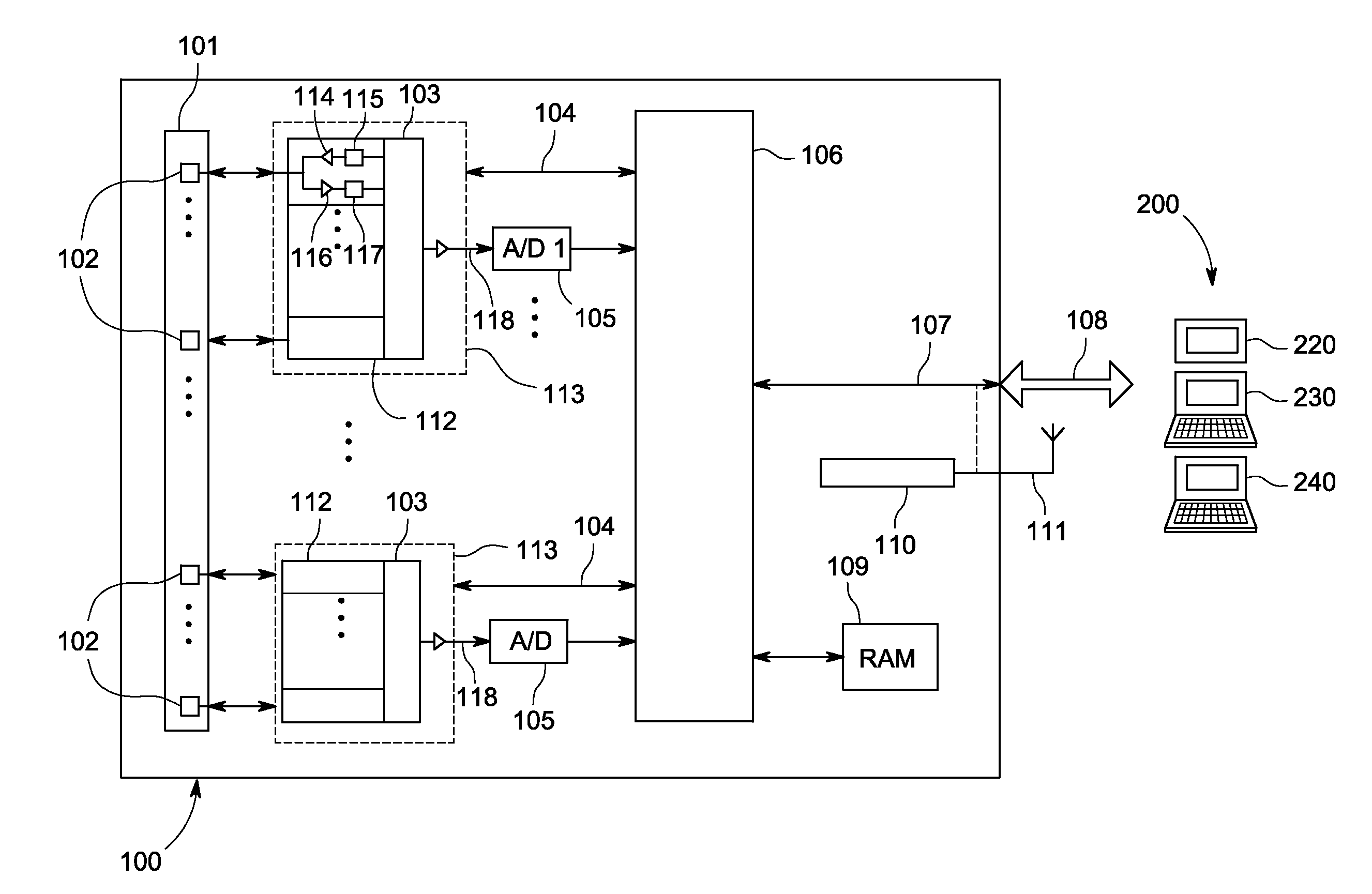
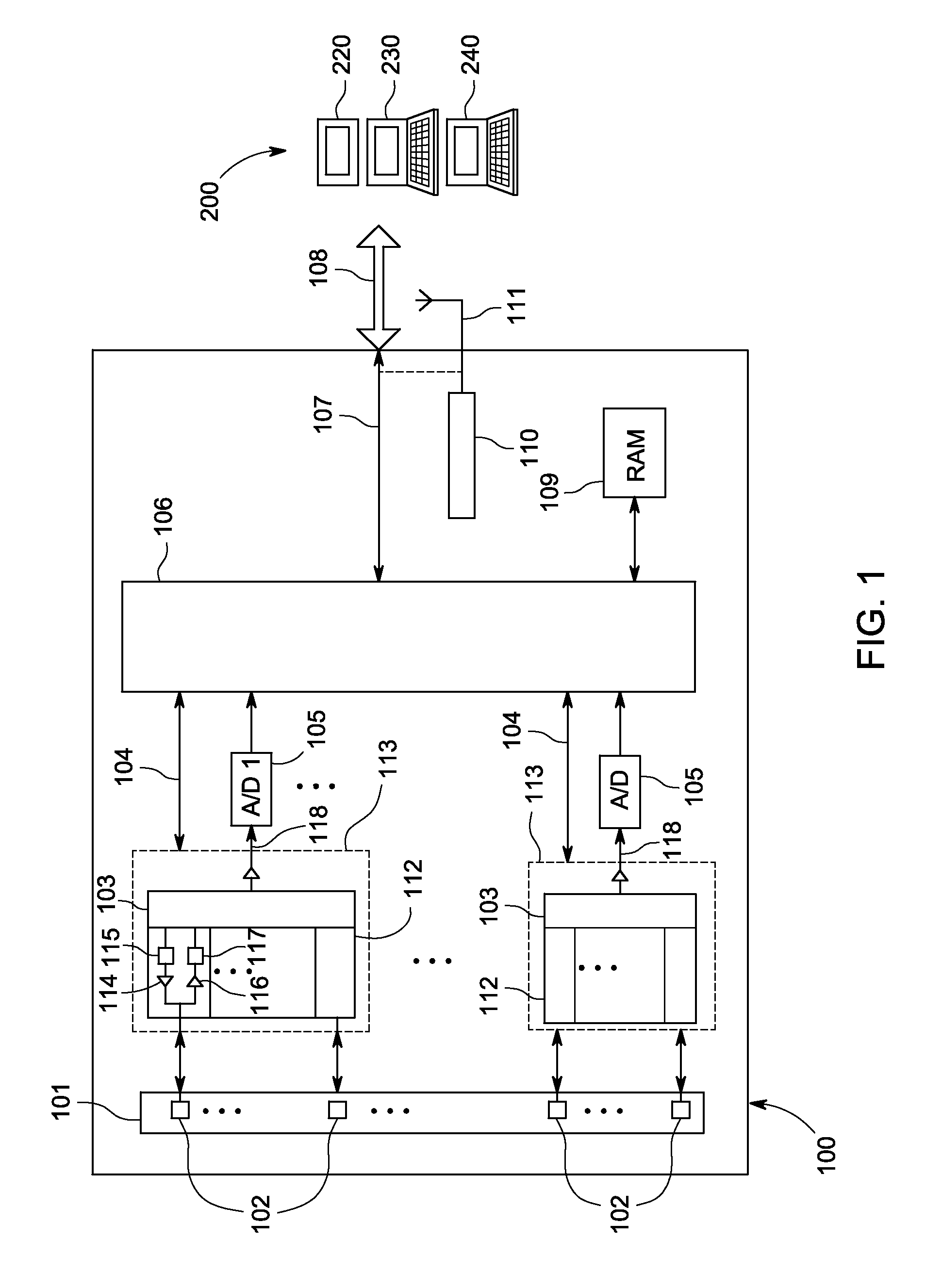
[0016]FIG. 1 illustrates an integrated active ultrasonic probe 100. In one embodiment, the integrated active ultrasonic probe 100 comprises an array 101 of ultrasonic transducers 102 each electrically connected to a transmitter and receiver circuit 112. The transmitter portion of the transmitter and receiver circuits 112 each comprise a pulser 114 that transmits electrical pulses to a connected one of the ultrasonic transducers 102. The pulsers 114 generate electrical pulses coordinated by control circuit 103 and buffered in transmitter delay circuits 115, including delays for controlling beam steering.

[0017]The receiver portion of the transmitter and receiver circuits 112 comprises an amplifier 116 and receiver delay 117 for receiving ultrasonic echoes detected by one of the connected ultrasonic transducers 102. In addition to controlling transmitter signals to the ultrasonic transducers 102, control circuit 103 sums the received echo data from all the transmitter and receiver circ...


PUM

PropertyMeasurementUnit
distanceaaaaaaaaaa
ultrasonic energyaaaaaaaaaa
ultrasonicaaaaaaaaaa

Abstract

An ultrasonic probe includes ultrasonic transducers and processing electronics to control emission of ultrasonic energy and to process and digitize returned echo data. Processed echo data can then be transmitted over a digital interface for display.

Description

BACKGROUND OF THE INVENTION[0001]The subject matter disclosed herein relates to ultrasonic probes, in particular, an integrated active ultrasonic probe that is connectable to a plurality of computing devices.[0002]Nondestructive testing devices can be used to inspect, measure, or test objects to identify and analyze anomalies in the objects. These devices allow an inspection technician to maneuver a probe at or near the surface of the test object in order to perform testing of both the object surface and its underlying structure. Nondestructive testing can be particularly useful in some industries, e.g., aerospace, power generation, and oil and gas transport or refining (e.g., pipes and welds). The inspection of test objects must take place without removal of the object from surrounding structures, and where hidden anomalies can be located that would otherwise not be identifiable through visual inspection. Ultrasonic testing is one example of nondestructive testing. When conducting ...

Claims


Application Information

Patent Timeline
Patent Type & Authority Patents(United States)
IPC IPC(8): G01S15/89G01S7/52G01N29/44G01N29/24
CPCG01N29/24G01N29/44G01S7/5208G01N2291/106
Inventor BUECHLER, JOHANNES GEORG RUDOLFOBERDOERFER, YORKJOBST, MATTHIAS
Owner BAKER HUGHES INC
Why Eureka
Try Eureka