Method and apparatus for diverting material

a material and method technology, applied in the direction of mechanical conveyors, rolling carriages, loading/unloading, etc., can solve the problems of material falling off the second conveyor belt, damage to the conveyor belt surface, cuts and/or holes in the conveyor belt surface, etc., to reduce material spillage, reduce impact damage to the conveyor belt, and convenient, adaptable, and effective

Inactive Publication Date: 2007-08-21
MARTIN ENG
View PDF12 Cites 16 Cited by
  • Summary
  • Abstract
  • Description
  • Claims
  • Application Information

AI Technical Summary

Benefits of technology

[0010]The present invention is directed to an apparatus and associated method that satisfies the need for an inexpensive, convenient, adaptable, durable, and effective tool for reducing impact damage to conveyor belts and for reducing material spillage at transfer points. It can minimize conveyor belt damage, premature roller failure, and clean-up of spilled material, thereby extending the useful life of conveyor belts and associated equipment. It can also eliminate the need for newly-designed costly chutes, impact beds, and external skirt boards. An embodiment of the apparatus of the present invention comprises a diverter plate and a mounting assembly. The diverter plate provides a path upon which material falling through a conveyor belt transfer point chute from a first conveyor belt falls and is diverted such that the material subsequently falls more gently in a controlled manner onto a second conveyor belt. The diverter plate is made out of any sufficiently durable material, such as metal, plastic, and / or composites, that is suitable for use with the material being conveyed. The diverter plate also has a length, width, and thickness that is compatible with the dimensions of the chute and the weight of the material being conveyed. The diverter plate additionally has a shape that facilitates diversion of the conveyed material in a desired fashion. Thus, the diverter plate can be V-shaped, concave, flat, or any similar shape, depending on the type and size of chute and / or depending on the conveyed material. The diverter plate may have vertical sides, and may have a vibrator to assist in the flow of the material.
[0011]The diverter plate is positioned in, on, or under the chute using the mounting assembly. The mounting assembly is adjustable from outside the chute such that the angle of the diverter plate can be easily and conveniently set and thereafter changed. For example, the diverter plate may be positioned horizontally or may be angled downward toward the second conveyor belt. The mounting assembly comprises a carrier spring assembly and an adjustable locking mount. The carrier spring assembly, in turn, comprises a bracket to which the diverter plate is attached, a spring that permits resilient rotational motion of the bracket, and a shaft around which the bracket rotates. The adjustable locking mount adjustably fixes the shaft in a desired position relative to the chute. The adjustable locking mount comprises a base plate assembly that attaches the mounting assembly to the chute, a bushing that guides the shaft, and an external locking disc assembly that adjusts the positioning of the shaft. A dust seal placed around the adjustable locking mount where it contacts the chute minimizes dust emissions emanating from within the chute.
[0012]In use, the apparatus of the present invention absorbs the impact of material falling through the chute and diverts the flow of the material in a desired direction onto the second conveyor belt such that wear and tear on the second conveyor belt is minimized. As the material falls onto the diverter plate of the apparatus, the force of the falling material rotates the bracket about the shaft thereby pushing a bottom end of the diverter plate downward toward the second conveyor belt in an unload position. This pivoting action of the diverter plate thereby facilitates the flow of the material off the edge of the bottom end of the diverter plate and onto the second conveyor belt. The spring continually urges the bracket to counter-rotate back to its original, default position. The diverter plate is adjustable in height and angle relative to the second conveyor belt using the adjustable locking mount.
[0013]Thus, the apparatus of the present invention is an adjustable, impact absorbing material diverter and flow control device. It is easy to install on existing chutes, and it is easy to adjust from outside the chute such that the angle of the diverter plate can be positioned to minimize impact force on the second conveyor belt by the falling material.

Problems solved by technology

A frequent problem encountered when using conventional transfer point equipment is that when the material hits the second conveyor belt under the chute, the force of the material impacting against the second conveyor belt causes belt damage such as cuts and / or holes in the conveyor belt surface.
Although conventional impact beds and impact rollers provide some degree of conveyor belt protection through impact absorption, they are not designed to slow and / or redirect the flow of the falling material in order to provide significantly increased levels of conveyor belt impact protection.
Another problem often encountered with the use of conventional transfer point equipment is that some of the material tends to fall off of the second conveyor belt.
Although an external skirt board is generally used at transfer points to try to seal the conveyor belt, the material usually hits the second conveyor belt with such a high force that the material blows out the back and sides of the external skirt board.
This leads to lost material, increased clean-up costs, and damage to external skirt boards and other nearby equipment.
Conveyor belt cover damage is very costly to repair.
Cuts in the surface trap material that later comes out of the cuts and can accumulate on the conveyor belt rollers, thereby damaging the rollers and requiring costly roller replacement.
Adjusting and / or replacing worn out external skirt board is costly as well.
Such attempts to solve the aforementioned problems associated with conventional conveyor belts and transfer points are not only very costly in and of themselves, there is also no convenient method for making adjustments to these pre-manufactured fixed chutes without major cost expenditures.

Method used


Image

  • Method and apparatus for diverting material
  • Method and apparatus for diverting material
  • Method and apparatus for diverting material

Examples


Embodiment Construction

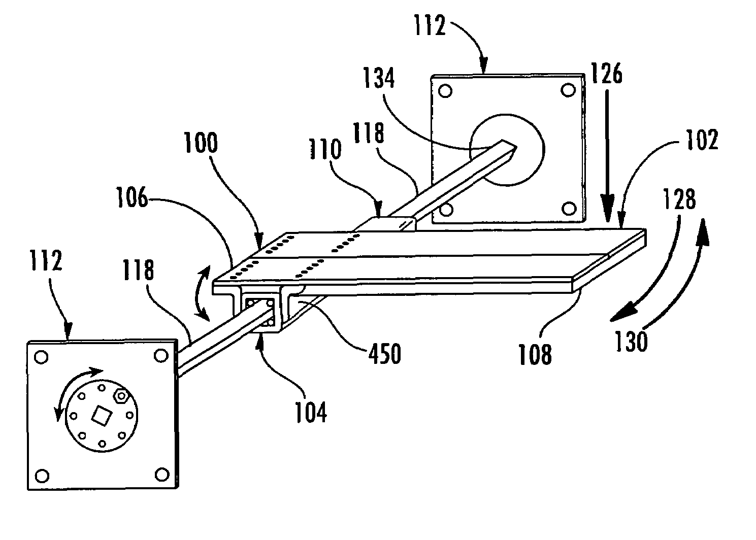
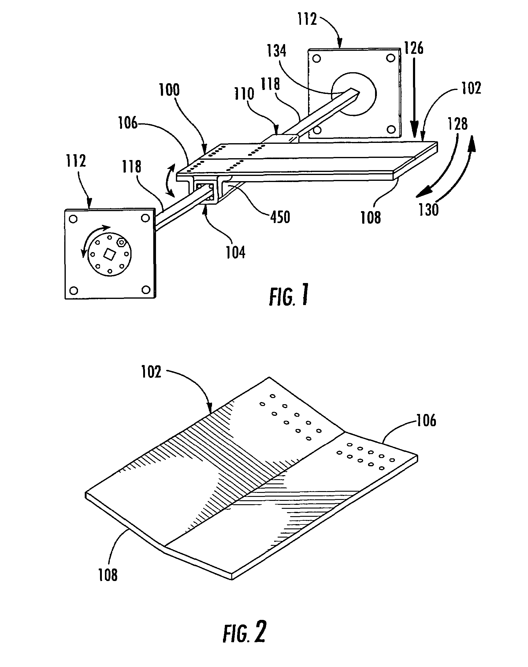
[0036]As shown in FIG. 1, the flow control apparatus 100 comprises a diverter plate 102 attached to a mounting assembly 104. The diverter plate 102 has a top end 106 and a bottom end 108. The diverter plate 102 has a flat or planar rectangular shape, a V-shape with a trough along the midline of the length of the diverter plate 102, a concave shape with a trough along the length of the diverter plate 102, or a similar shape that facilitates a flow of conveyed material along the length of the diverter plate 102 such as U-shaped, cup shaped, or spoon shaped. The diverter plate 102 may also have vertical sides. One embodiment of the diverter plate 102 as shown in FIG. 2 comprises a rectangular stainless steel plate with a thickness of about one-half of an inch, a width of about twenty-four inches, a length of about thirty inches, and a V-shaped trough along the midline of the length of the diverter plate 102 having an internal angle of about one hundred sixty-one degrees. The diverter p...


PUM


Abstract

An apparatus for diverting material in a controlled manner comprising a diverter plate attached to a mounting assembly. The diverter plate is shaped for receiving falling material and facilitating the flow of the material onto a conveyance means or into storage. The mounting assembly comprises a carrier spring assembly that permits the diverter plate to pivot about a shaft and thereby move from a default position to an unload position. The mounting assembly further comprises two adjustable locking mounts that hold the shaft in place and also allow the shaft to be adjustably rotated and thereafter fixed in place. A method for diverting material in a controlled manner comprises the steps of installing the apparatus at a transfer point and activating a first conveyance means that feeds material to the chute. A second conveyance means that receives the material after diversion by the apparatus can optionally be activated.

Description

CROSS-REFERENCES TO RELATED APPLICATIONS[0001]This application claims the benefit of U.S. Provisional Application Ser. No. 60 / 557,066 filed Mar. 26, 2004.BACKGROUND OF THE INVENTION[0002]1. Field of the Invention[0003]This invention relates to transfer points on conveyor belts or other means of conveyance, and more specifically, to an apparatus and method for diverting or directing the flow or movement of material from one means of conveyance such as a first conveyor belt to another means of conveyance such as a second conveyor belt or into storage.[0004]2. Description of the Related Art[0005]Conveyor belts are often used to transfer large quantities of materials, such as mineral ores, from one location to another. Transfer points are frequently needed at junction points between two such conveyor belts when the material must be transported in a new direction or at a lower elevation. At these transfer points, material dumps from an initial or first conveyor belt into a chute and onto...

Claims


Application Information

Patent Timeline
Patent Type & Authority Patents(United States)
IPC IPC(8): B65G11/00B65G47/34B65G11/20B65G37/00B65G69/04
CPCB65G11/206B65G47/44B65G69/0441B65G45/16B65G2201/045
Inventor HALL, JOHN
Owner MARTIN ENG
Why Eureka
Try Eureka