Structure of improved pneumatic gripper assemblies

a technology of pneumatic gripper and assembly, which is applied in the can solve the problems of not being adopted in the manufacture field of pneumatic gripper assembly, the construction process of similar gripper assembly is extremely laborious and painstaking, and the forming technique, although well established in practice, has never been adopted in the field of gripper assembly manufacturing, so as to reduce the machining and assembling time and cost. , to achieve the effect of reducing the time and cost o

Inactive Publication Date: 2007-08-21
GIMATIC SRL
View PDF15 Cites 9 Cited by
  • Summary
  • Abstract
  • Description
  • Claims
  • Application Information

AI Technical Summary

Benefits of technology

[0007]This invention has been conceived to meet the above-mentioned requirement and to be able to take good advantage of the forming techniques of the items referred to above also in the manufacture of pneumatic gripper assemblies and to create the conditions to eliminate or at least minimise machining and assembling times and costs.
[0009]Another objective of the invention is the realisation of pneumatic gripper assemblies, each one made up of a limited number of pre-formed elements capable of fitting complementarily one with the other and with inserted auxiliary elements, ensuring the functionality of the resulting group improving in fact performance and life.
[0010]A further objective of the invention is to supply a linear or angular pneumatic gripper assembly which is easy to set up using a “sandwich” type assembly of the supporting and functional components.

Problems solved by technology

As the technicians in this sector are well aware, the construction process of similar gripping assemblies is extremely laborious and painstaking due to the machining and operating times needed and often because of the fine tolerances required.
These forming techniques, although well established in practice, have never been adopted in the gripper assembly manufacture field or if used only limited to basic components also because the configuration of the elements of these grippers, used in the traditional way, do not enable it.

Method used


Image

  • Structure of improved pneumatic gripper assemblies
  • Structure of improved pneumatic gripper assemblies
  • Structure of improved pneumatic gripper assemblies

Examples


Embodiment Construction

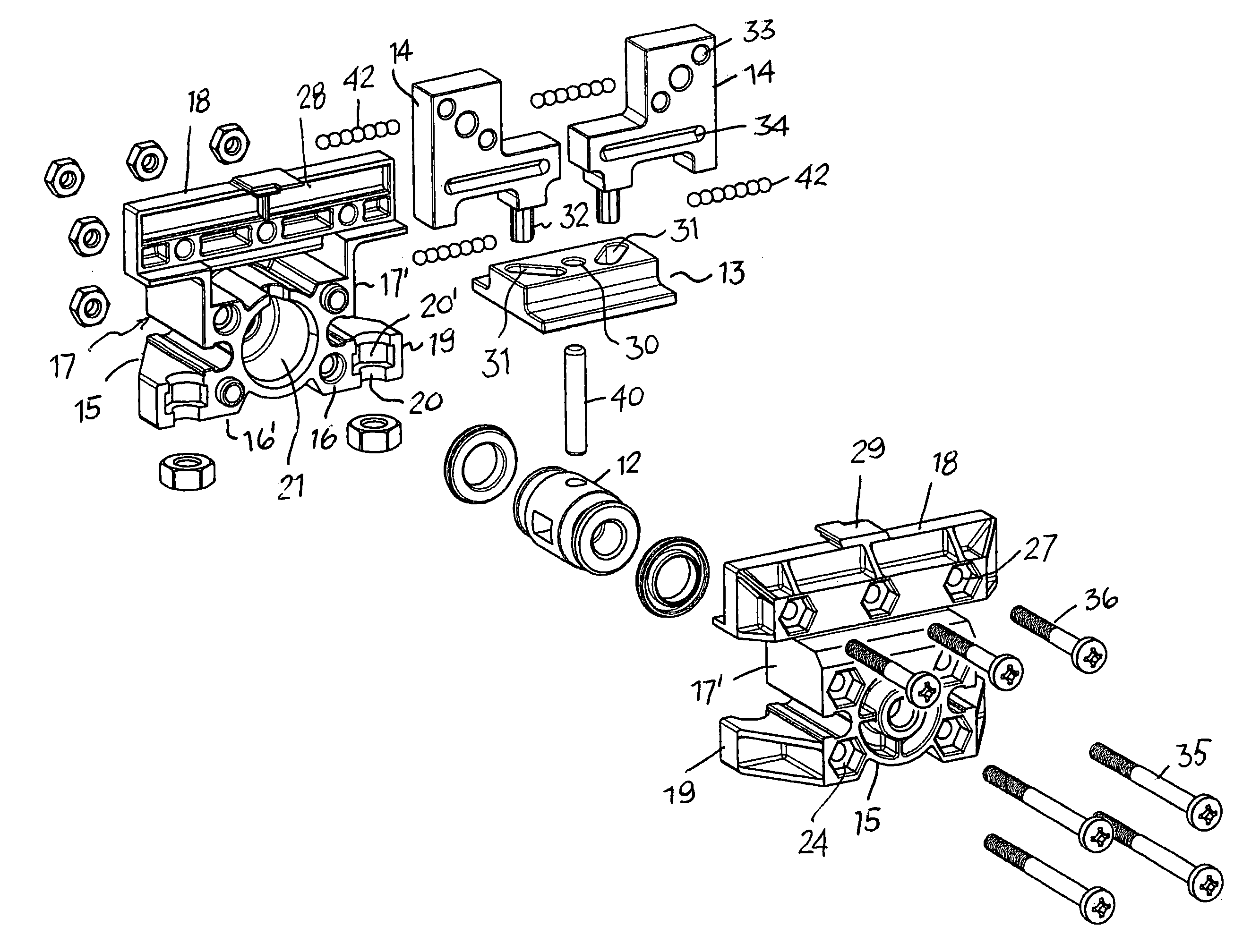
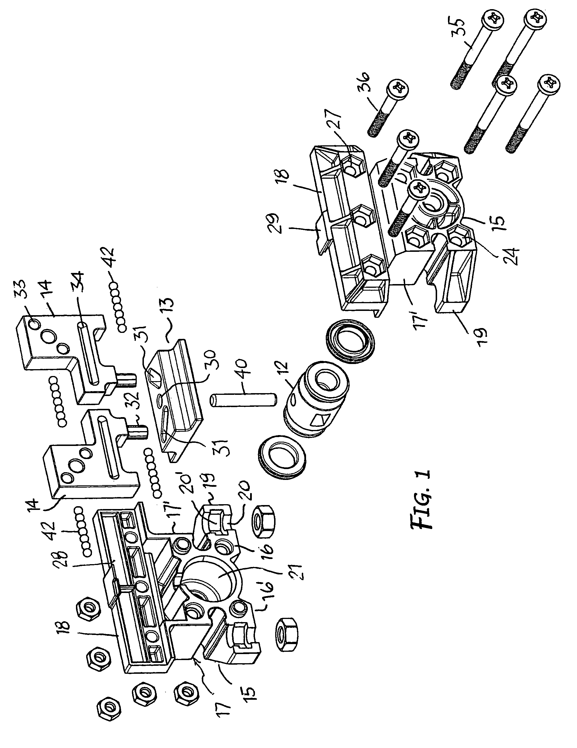
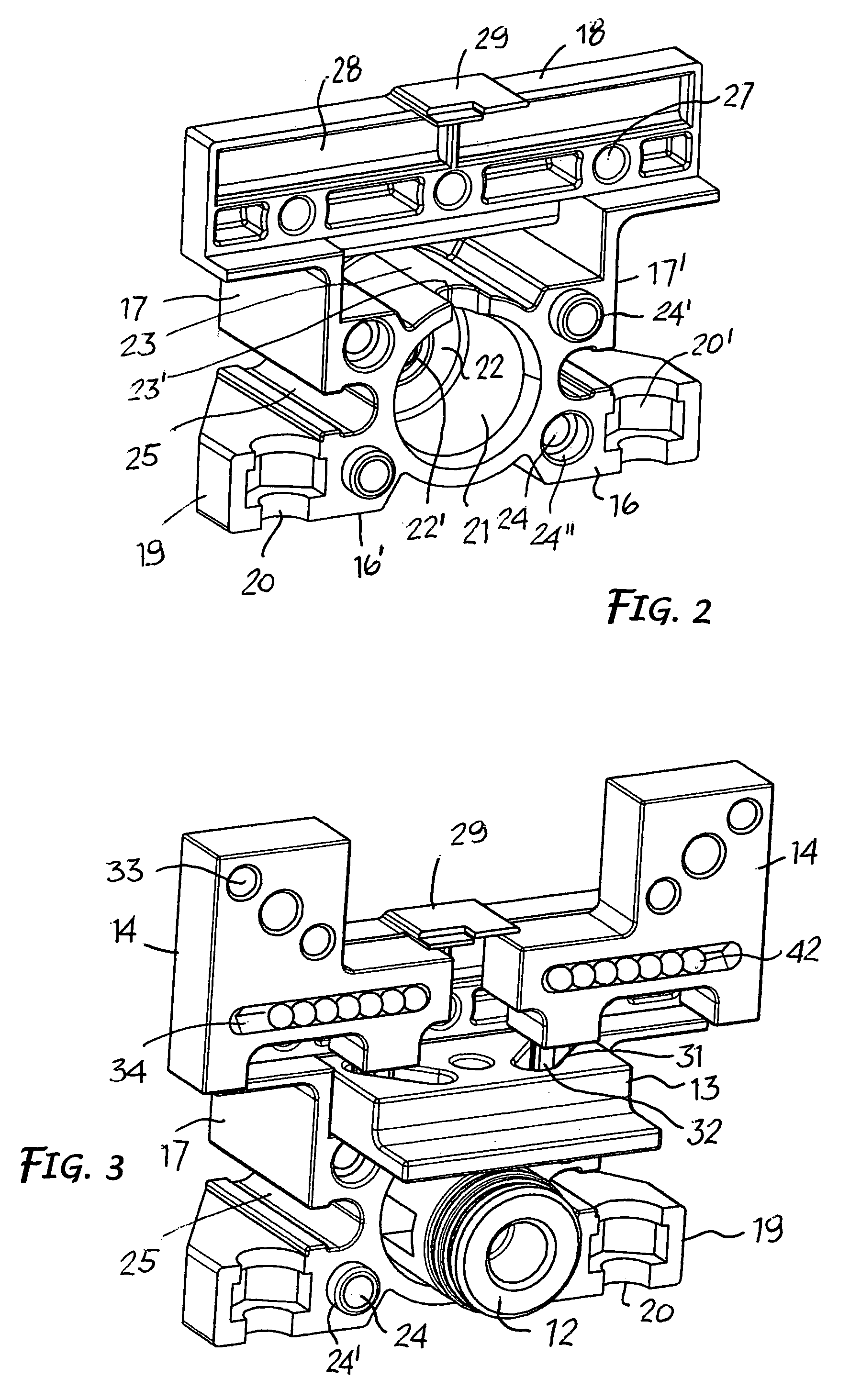
[0026]Both the linear and angular pneumatic gripper assembly represented comprises a supporting body 11, an alternating piston 12 moving in said body, a drive system 13 associated with the piston and two jaws 14 driven by the piston, moving in opposite directions by means of the drive system 13 and each one can be equipped with jaw shoes not shown. The only difference between the two types of pneumatic grippers is that the jaws in the linear grippers are subjected to rectilinear movements in opposite directions, whereas in the angular grippers the jaws turn each one on a pin, performing angular movements in opposite directions in response to the movements of the piston.

[0027]According to a construction method as illustrated in FIGS. 1-7, the supporting body 11 is made up of two exactly equal elements or symmetric half-bodies or shells 15. They therefore can be made advantageously from the same mould, using die-casting, sintering or a forging systems in any appropriate material.

[0028...


PUM


Abstract

The invention relates to a pneumatic gripper assembly structure which comprised a supporting body (11, 111) composed of at least two wall elements or symmetrical half-shells (15, 115), realized and finished individually using a forming process and then put together to form a single body capable of receiving, supporting and guiding other structural and functional components of the gripper assembly. The complementary wall elements or half-bodies are produced using die-casting, sintering or forging techniques with material compatible for such processes and provides a housing for jaws and a drive piston of the gripper.

Description

FIELD OF INVENTION[0001]This invention concerns pneumatic gripper assemblies in general used for securing items being machined and / or for automatic manipulation, and refers in particular to improved components for setting up such assemblies.STATE OF THE ART[0002]Both linear and angular pneumatic grippers, of the type taken into consideration here, are well known as regards to structure and functioning. They can be of different shapes, sizes and capacity, but each one is made up essentially of a supporting body, a simple or double-acting piston, moving either in a chamber or jacket in said body, and two jaws supported and guided in the body, working in conjunction with the piston, moving straight or at an angle in opposite directions in response to the alternating movements of the piston and supporting two item gripper jaw.[0003]According to the known techniques, the components of said pneumatic gripper assemblies are machined on tool machines. In particular the body of a pneumatic g...

Claims


Application Information

Patent Timeline
Patent Type & Authority Patents(United States)
IPC IPC(8): B25J15/08B23Q3/06B25B5/06B25B5/08B25J15/02
CPCB25B5/061B25B5/087B25J15/0206B25J15/0253B25J15/028
Inventor BELLANDI, GIUSEPPEMAFFEISI, GIUSEPPE
Owner GIMATIC SRL
Why Eureka
Try Eureka