Fluid delivery device identification and loading system

a technology of delivery device and loading system, which is applied in the direction of positive displacement liquid engine, pump control, other medical devices, etc., can solve the problems of insufficient monitoring means, few if any physical elements, and inability to ensure the proper and complete seating of the cassette to the pump

Active Publication Date: 2007-08-21
ICU MEDICAL INC
View PDF11 Cites 183 Cited by
  • Summary
  • Abstract
  • Description
  • Claims
  • Application Information

AI Technical Summary

Problems solved by technology

These previous pumps often have few if any physical elements to ensure proper cassette orientation to the pump.
They also do not ensure proper and complete seating of the cassette to the pump.
Additionally, they have insufficient means for monitoring if the cassette was indeed oriented correctly and / or fully seated to the pump.

Method used


Image

  • Fluid delivery device identification and loading system
  • Fluid delivery device identification and loading system
  • Fluid delivery device identification and loading system

Examples


Embodiment Construction

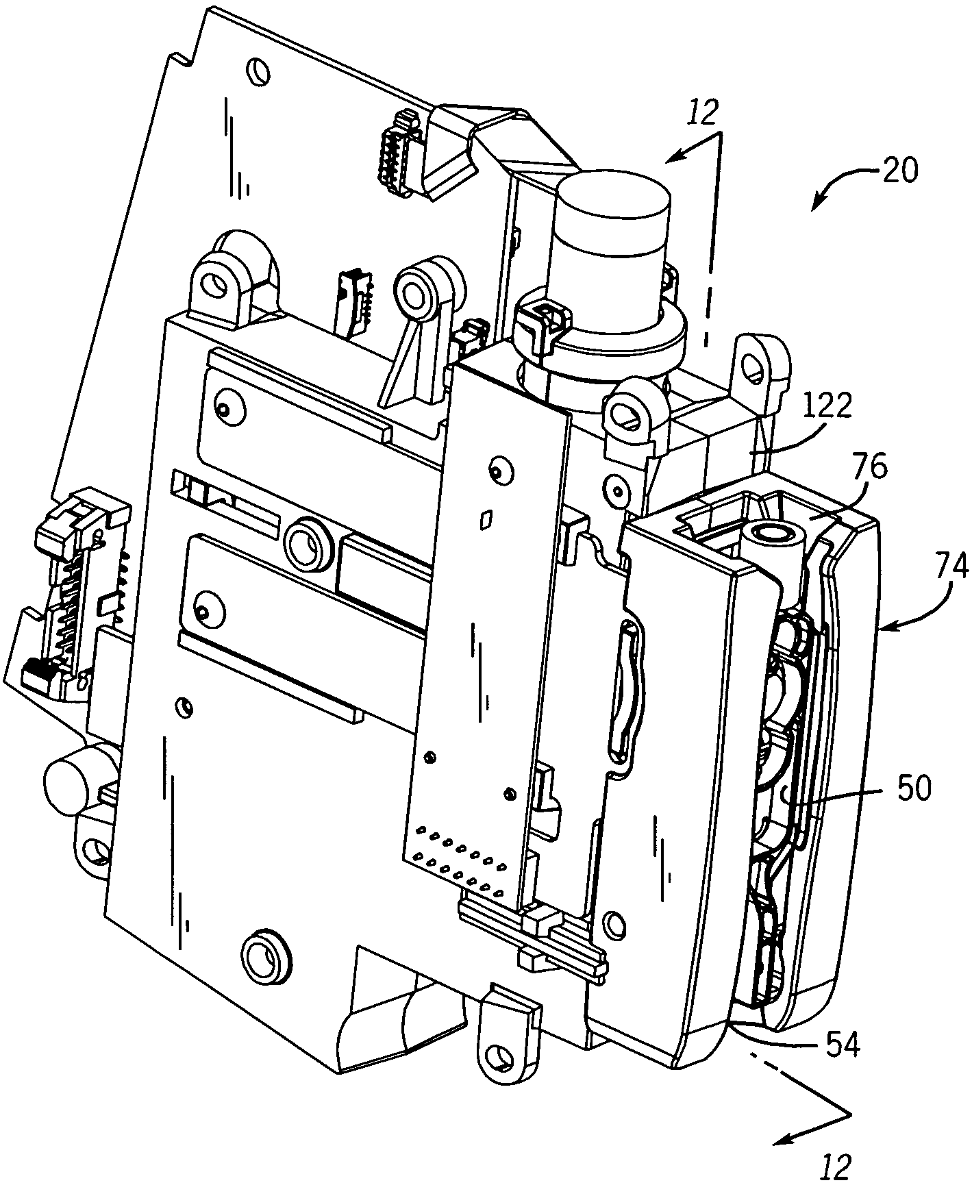
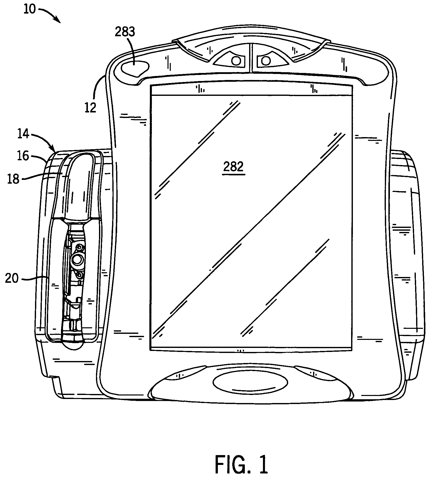
[0036]With reference to FIG. 1, a medical pump 10 is shown having a housing 12 and an infuser mechanism 14 attached to the housing 12. The infuser mechanism 14 includes an infuser cover 16, an indicator window 18 attached to the infuser cover 16, and a loader 20 for a fluid delivery device, including but not limited to a cassette, syringe, and / or tubing. The loader 20 is attached to the infuser cover 16 immediately below the indicator window 18.

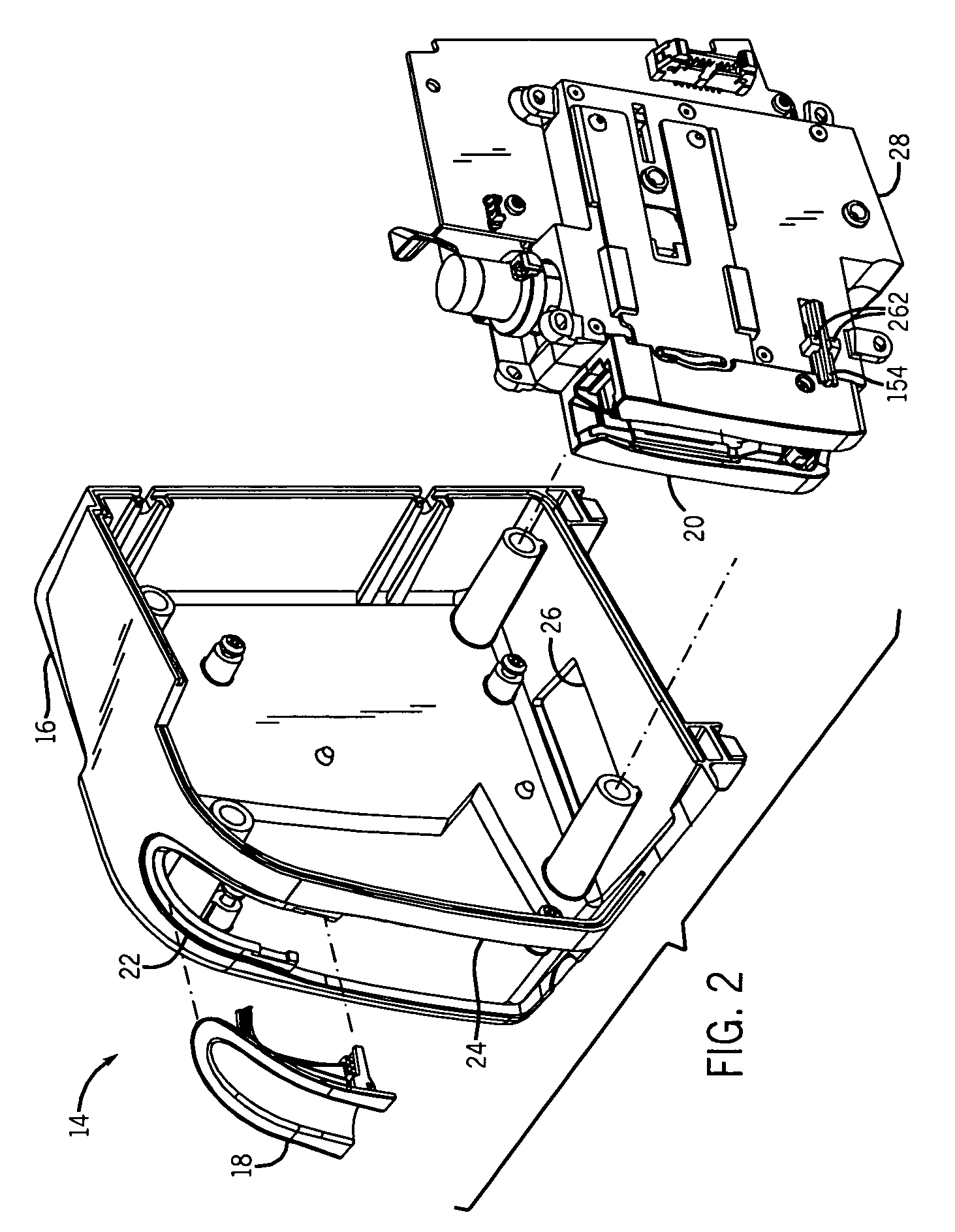
[0037]With reference to FIG. 2, indicator opening 22, loader opening 24, and manual release opening 26 are all formed in the infuser cover 16. The indicator opening 22 permits insertion and attachment of the indicator window 18 to the infuser cover 16. Likewise, the loader opening 24 permits insertion and attachment of the loader 20 to the infuser cover 16. The manual release opening 26 permits insertion and attachment of a manual release portion 28 of the loader 20 to the infuser cover 16.

[0038]With reference to FIGS. 3 and 4, a window body ...


PUM


Abstract

A medical pump includes a chassis having a fixed seat, and a main carriage having a carriage footing for receiving a fluid delivery device and restricting its movement. An actuator automatically moves the main carriage between open and closed positions to engage the fluid delivery device to the seat. The seat establishes the position of both the main carriage and fluid delivery device in the closed position. The actuator is connected to the main carriage by a rear carriage assembly having a manual release element for disengaging the actuator from rear carriage assembly and thereby from the main carriage. A processing unit detects jam conditions by processing carriage position data and electrical load data from the actuator.

Description

BACKGROUND OF THE INVENTION[0001]The present invention relates to a means of automatically loading and unloading a pump cassette or other fluid delivery device into a medical pump.[0002]Modern medical care often involves the use of medical pump devices to deliver fluids and / or fluid medicine to patients. Medical pumps permit the controlled delivery of fluids to a patient, and such pumps have largely replaced gravity flow systems, primarily due to the pump's much greater accuracy in delivery rates and dosages, and due to the possibility for flexible yet controlled delivery schedules. Of the modern medical pumps, those incorporating a diaphragm cassette are often preferred because they provide more accurately controlled rate and volume than do other types of pumps.[0003]A typical positive displacement pump system includes a pump device driver and a fluid delivery device, including but not limited to a syringe, tubing, section of tubing, or a disposable cassette. The disposable cassett...

Claims


Application Information

Patent Timeline
Patent Type & Authority Patents(United States)
IPC IPC(8): F04B43/08A61M5/14A61M5/142
CPCA61M5/14224A61M5/1413A61M2205/12A61M2205/14A61M2205/3351A61M2205/3355A61M2205/6045A61M2205/6081
Inventor FATHALLAH, MARWAN A.ZIEGLER, JOHN S.FRANCHINO, DAVID C.CHASE, KENT B.BAKKEN, TODD J.LEE, DANIEL J.
Owner ICU MEDICAL INC
Why Eureka
Try Eureka