
Reinforced lacrosse head

Active Publication Date: 2007-08-21
WARRIOR LACROSSE
View PDF12 Cites 36 Cited by
  • Summary
  • Abstract
  • Description
  • Claims
  • Application Information

AI Technical Summary

Benefits of technology

[0007]One advantage of the present invention is to provide a reinforced lacrosse head that has increased strength and resistance to deformation or breakage.
[0008]Another advantage of the present invention is to provide a reinforced lacrosse head that has increased strength and is still substantially lightweight as compared to current lacrosse heads, which yields decreased material and manufacturing costs.
[0009]Yet another advantage of the present invention is to provide a reinforced lacrosse head that requires less plastic, thereby decreasing the amount of time required for cooling the plastic and consequently decreasing the overall manufacturing cycle time of the lacrosse head.
[0010]In accordance with the above and the other advantages of the present invention, the present invention provides a reinforced lacrosse head having a substantially strong construction for resisting deformation or breakage. The reinforced lacrosse head includes a pair of opposing sidewall portions each having a top end and a bottom end, a scoop portion extending between the sidewall portions, a base portion extending between the bottom ends of the sidewall portions, and a throat portion extending from the base portion for attachment to a lacrosse handle. In one embodiment, the sidewall portions have an open sidewall construction in that each sidewall portion is comprised of one or more non-string hole openings formed therein. Each sidewall portion includes one or more stiffening ribs integrated therein for reinforcing the sidewalls adjacent the openings in the sidewalls. Furthermore, the reinforced lacrosse head includes one or more reinforcement members that are insert-molded within the stiffening ribs. In an alternate embodiment, one or more reinforcement members can be insert molded into the scoop portion, the base portion, and / or the throat portion.

Problems solved by technology

A drawback of the open-frame construction is that it can create structural weaknesses within the lacrosse head and allow the lacrosse head to twist, bend, otherwise deform, or even break.
Unfortunately, however, these stiffening ribs may not be sufficiently strong for preventing the deformation or the breakage of the lacrosse head.
Alternatively, they can add too much material and thus weight to the lacrosse head, thereby yielding an undesirable lacrosse head.

Method used


Image

  • Reinforced lacrosse head
  • Reinforced lacrosse head
  • Reinforced lacrosse head

Examples


Embodiment Construction

[0017]In the following figures, the same reference numerals are used to identify the same components in the various views.

[0018]The present invention is particularly suited to a lacrosse head having sidewall portions with an open-frame construction and with one or more reinforcement members insert-molded therein. For this reason, the embodiments described herein utilize features where the context permits. However, various other embodiments without the described features are contemplated as well. In other words, the present invention can be carried out in various other modes as desired. Moreover, the present invention can be utilized with a variety of differently configured lacrosse heads, including non-open sidewall lacrosse heads and straight-walled lacrosse heads.

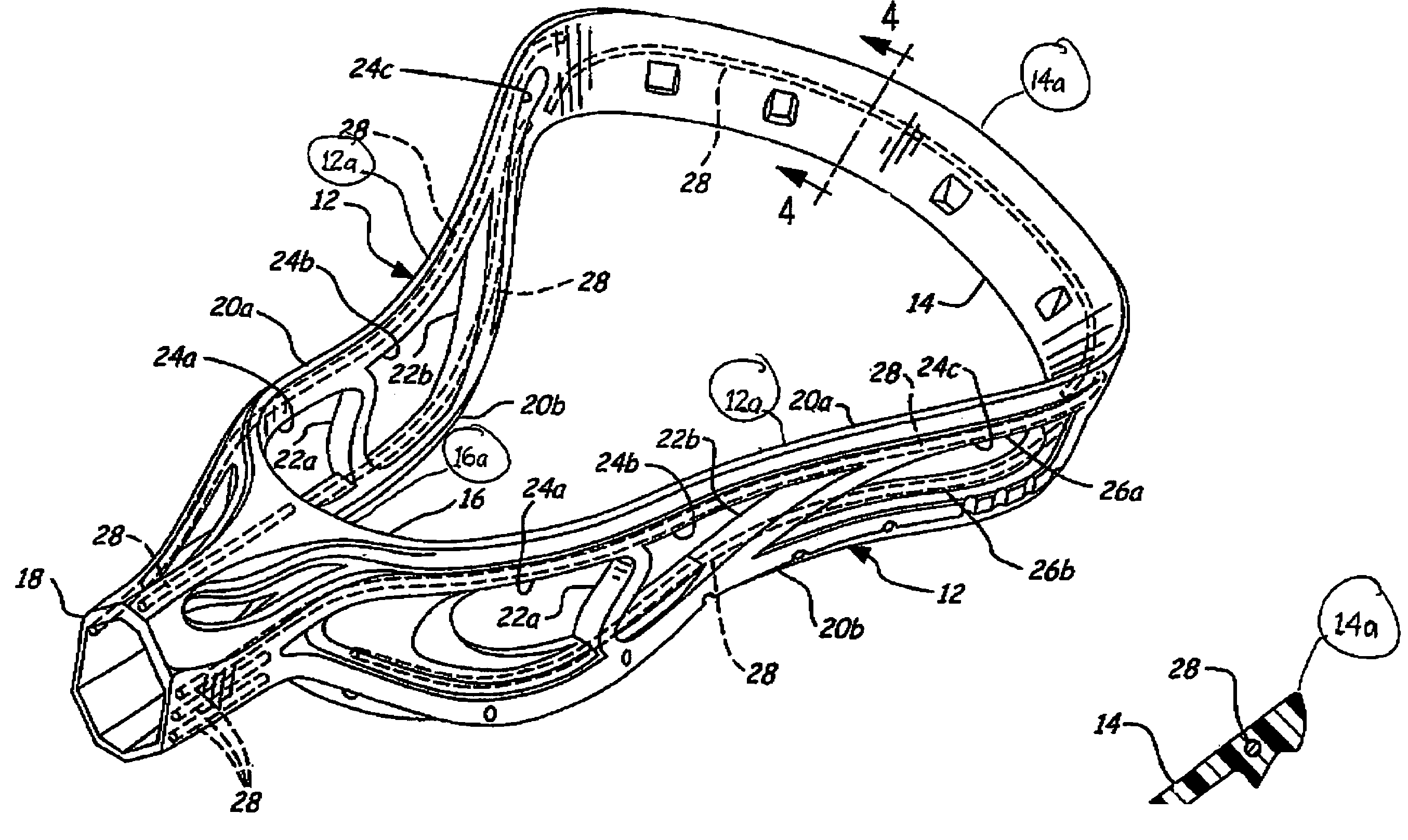
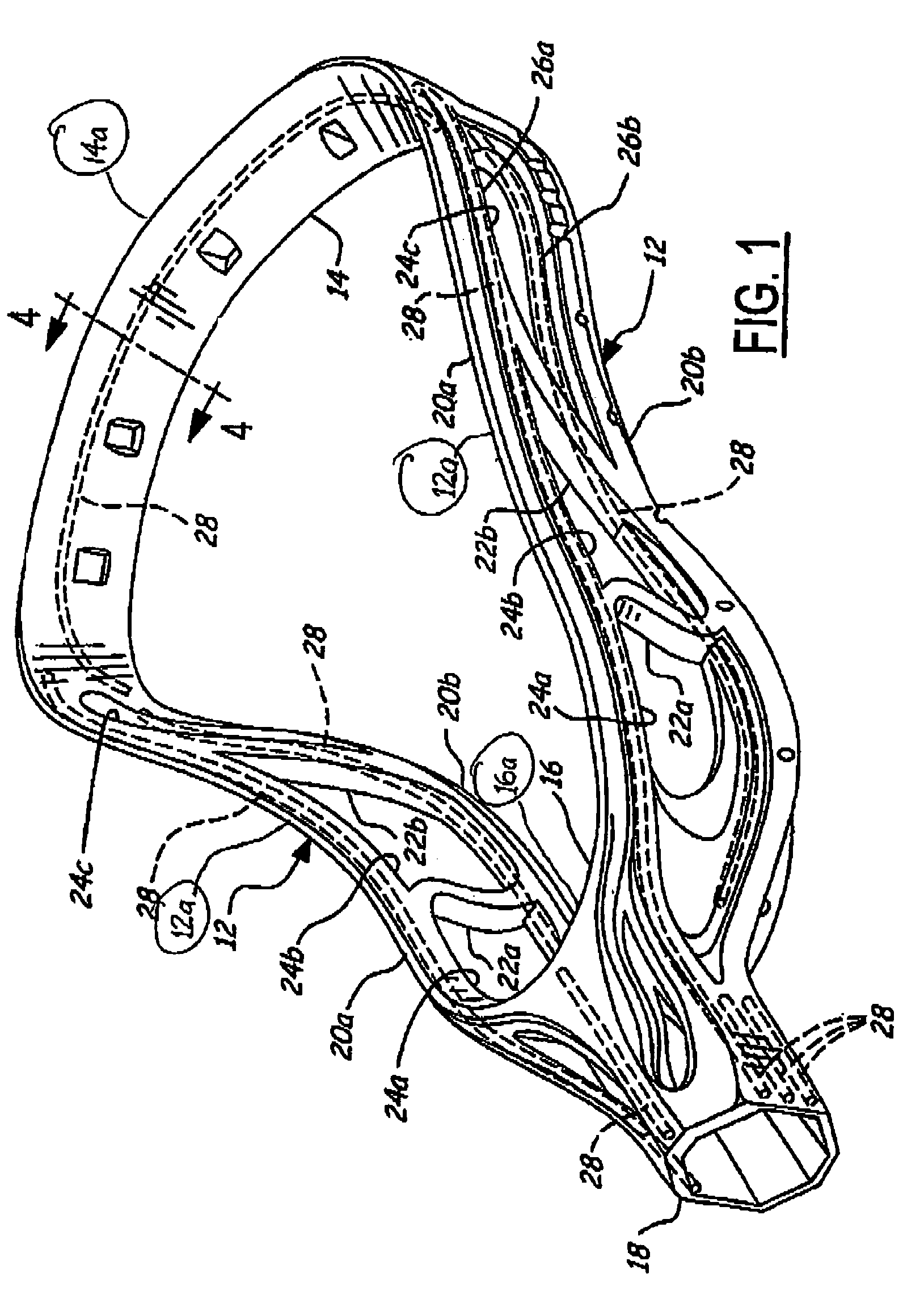
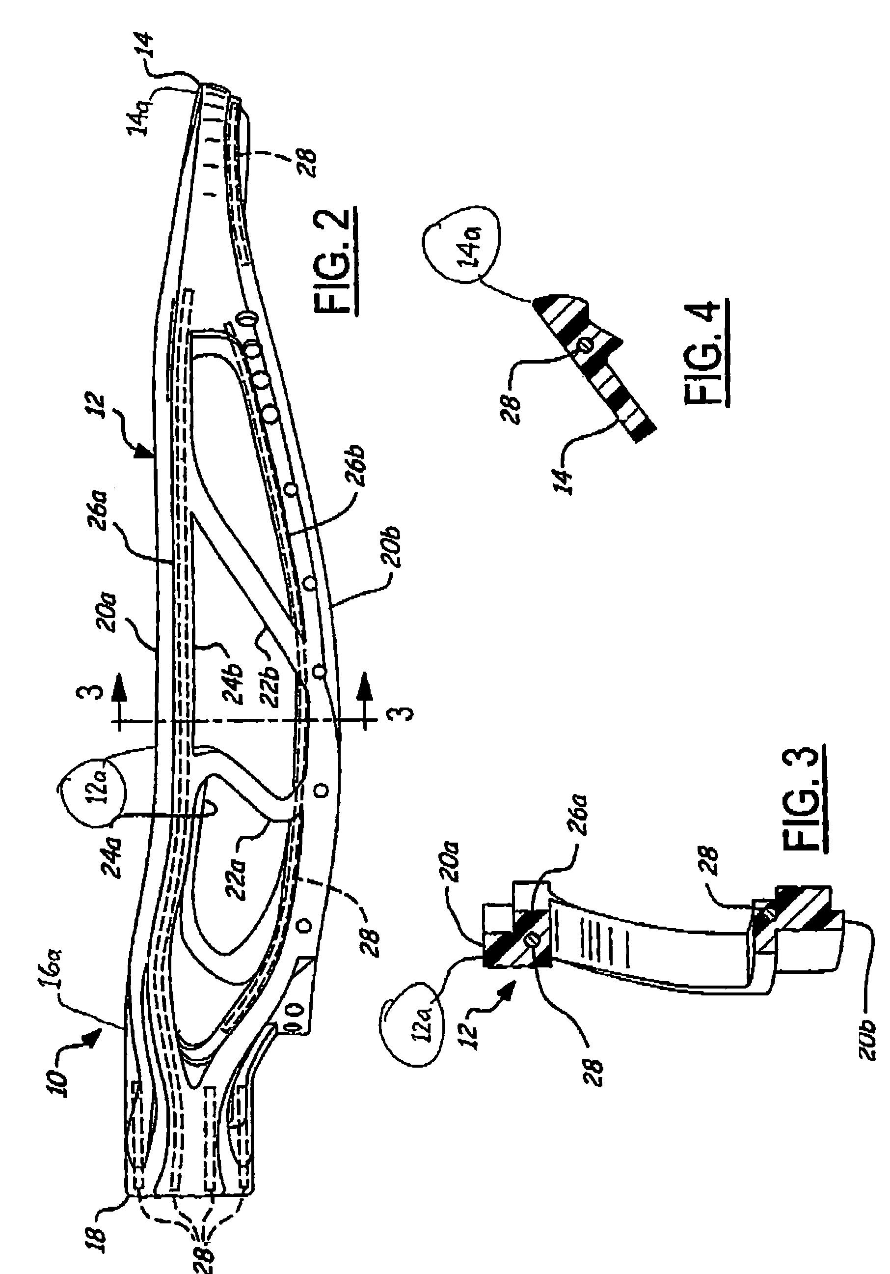
[0019]Referring to FIGS. 1 and 2, there is shown a reinforced lacrosse head 10 according to one embodiment of the present invention. The reinforced lacrosse head 10 is preferably a one-piece injection-molded frame element...


PUM


Abstract

A reinforced lacrosse head having improved strength includes a pair of opposing sidewall portions each having a top end and a bottom end, a scoop portion extending between the sidewall portions, a base portion extending between the bottom ends of the sidewall portions, and a throat portion extending from the base portion for attachment to a lacrosse handle. This reinforced lacrosse head has one or more reinforcement members that are coupled to one or more portions of the lacrosse head.

Description

CROSS-REFERENCE TO RELATED APPLICATION[0001]This application claims priority from U.S. Provisional Application Ser. No. 60 / 380,547, filed May 14, 2002 entitled “Stiffening Ribs For A Lacrosse Head,” the disclosure of which is incorporated by reference herein.TECHNICAL FIELD[0002]The present invention relates generally to a lacrosse head for attachment to a lacrosse stick, and more particularly to a lacrosse head having increased strength without increasing the weight of the lacrosse head.BACKGROUND OF THE INVENTION[0003]Lacrosse heads for use in the game of lacrosse are well known. Current lacrosse heads typically are manufactured by plastic injection molding processes and are secured to a lacrosse handle or stick for use in play. The structure of a typical lacrosse head is defined by a throat portion for connection to the lacrosse handle, a base portion that is disposed adjacent to the throat portion and defines a ball rest, a pair of opposing sidewall portions that generally diver...

Claims


Application Information

Patent Timeline
IPC IPC(8): A63B59/02A63B65/12
CPCA63B59/02A63B59/0088A63B2209/00A63B2243/005A63B2102/14A63B59/20A63B60/50
Inventor MORROW, DAVIDHUBBARD, JESSEMALISZEWSKI, ANDREWWINNINGHAM, MATTHEW
Owner WARRIOR LACROSSE
Learn More