
Automated glass entrance door assembly for walk-in coolers

a technology of automatic glass entrance doors and walk-in coolers, which is applied in the direction of heaters, lighting and heating equipment, furnaces, etc., can solve the problems of unsatisfactory manual swing doors, condensation present an unsightly appearance to customers, and conventional storefront automated entrance doors cannot be used for cooler entrance doors. , to prevent condensation, prevent convective heat loss and subsequent condensation formation, and prevent condensation

Active Publication Date: 2007-08-21
HUSSMANN CORP
View PDF7 Cites 32 Cited by
  • Summary
  • Abstract
  • Description
  • Claims
  • Application Information

AI Technical Summary

Benefits of technology

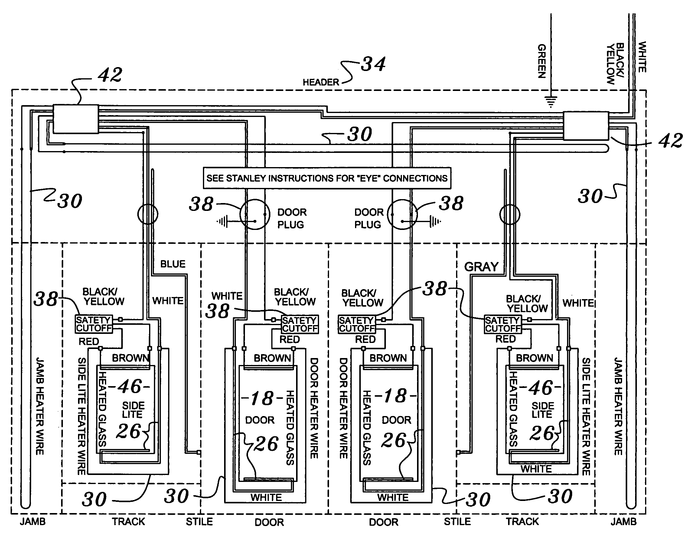
The invention is a special glass cooler entrance door that prevents condensation and puddling of water on the floor. It uses multiple panes of glass and frame materials with air pockets to keep the door surfaces above the dew point. The glass can also be heated and additional heat is provided in the door jambs and frames to maintain proper surface temperatures. Seals are incorporated at the sliding joints to prevent convective heat loss and subsequent condensation formation. This prevents safety hazards and premature failure of the electrical components. The invention can be used as a basis for modifying or designing other structures for carrying out the same purposes.

Problems solved by technology

Manual swing doors are undesirable, however, because the customer is preferably carrying a large amount of product such as a case of beer and cannot conveniently open the doors to exit the cooler.
It is well recognized that conventional storefront automated entrance doors cannot be used for cooler entrance doors because the temperature difference between the store and the cooler is so significant that condensation forms exteriorly on the doors and on the sliding glass door drive components located inside the header above the doors.
Not only does condensation present an unsightly appearance to the customer, it also presents a safety hazard to customers as the condensation puddles on the floor and leads to premature failure of the internal drive mechanism.
However, using a double set of automated entrance doors for a walk-in cooler requires too much valuable floor space and is cost prohibitive.

Method used


Image

  • Automated glass entrance door assembly for walk-in coolers
  • Automated glass entrance door assembly for walk-in coolers
  • Automated glass entrance door assembly for walk-in coolers

Examples


Embodiment Construction

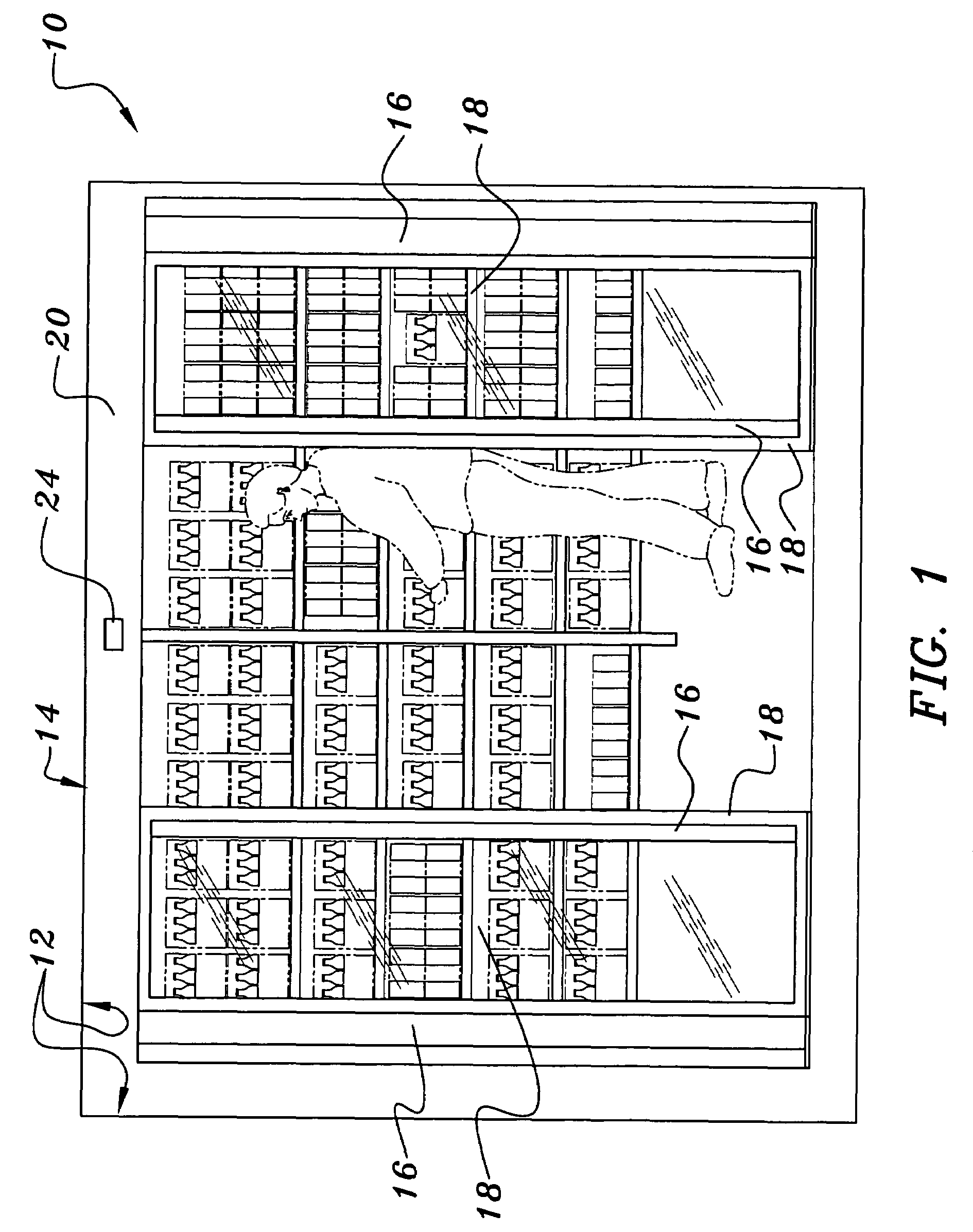
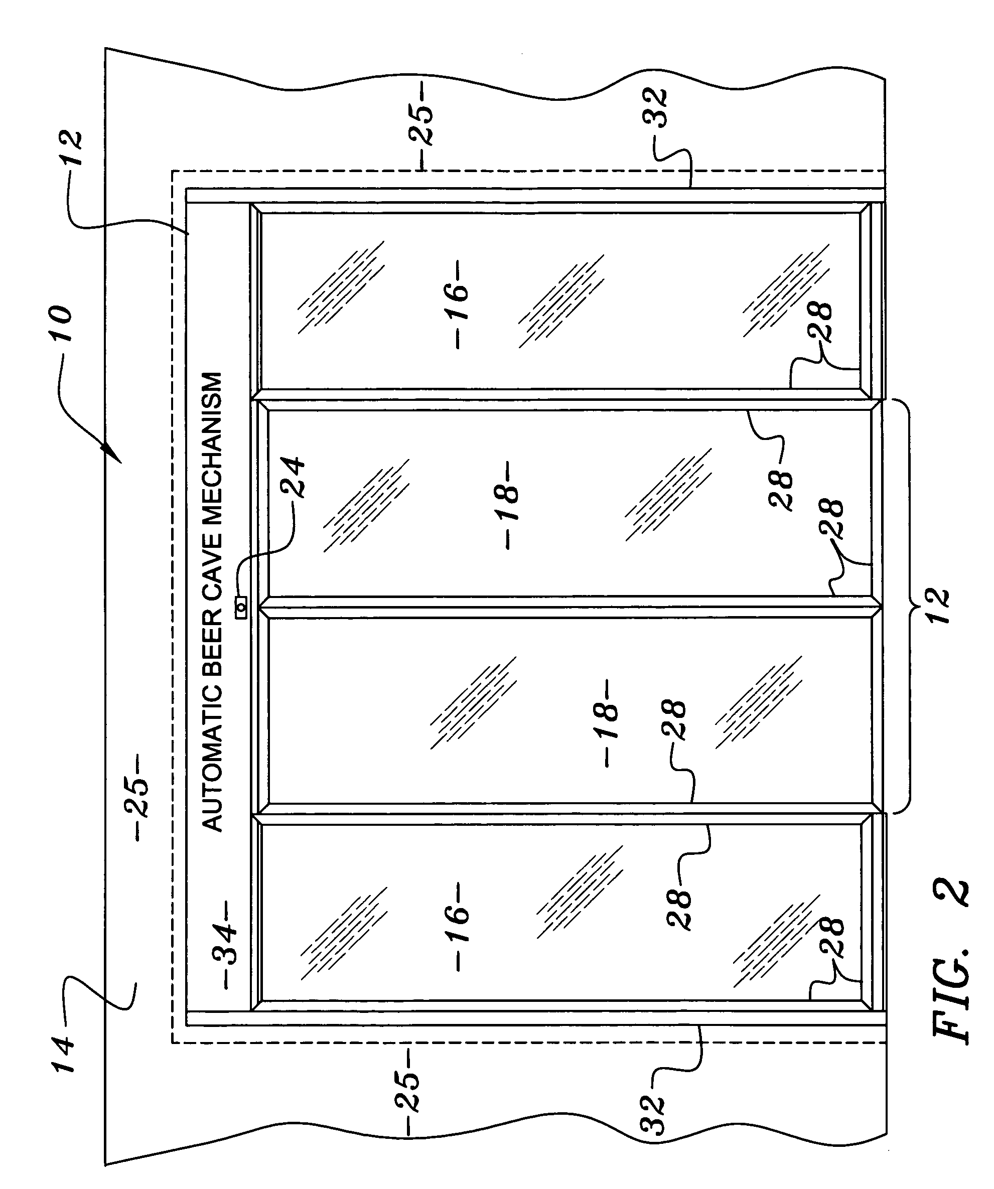
[0023]Referring to FIGS. 1 and 2, the automated glass cooler entrance door assembly 10 of the invention in intended to be installed within an opening 12 of a refrigerated walk-in cooler 14 in a convenience store or other retail establishment in which refrigerated beverages or other refrigerated products are typically sold. The automated glass cooler entrance doors assembly 10 comprises a pair of fixed, stationary glass side doors 16 that define a walkway about the opening 12 for ingress and egress into the cooler 14. A pair of opposing sliding glass doors 18 are operatively suspended from a concealed drive mechanism 20 above the opening 12 to slide sideways to and from a closed position across the opening 12 to close-off the cooler 14 from the rest of the store and then to and from an opened position overlapping the respective fixed stationary side doors 16 to allow a customer 22 ingress and egress to the cooler via the walkway through the opening 12.

[0024]An electric eye 24 positio...


PUM


Abstract

An automated glass cooler entrance door assembly for an opening in a walk-in cooler comprising at least one fixed, stationary side door that defines a walkway about the opening for ingress and egress into the cooler, at least one opposing sliding door operatively suspended from a concealed drive mechanism above the opening to slide sideways from a closed position across the opening to close-off the cooler to and from an opened position overlapping the fixed stationary side door to allow customer ingress and egress to the cooler via the walkway through the opening and each of the doors comprising heated glass that is electrically connected to electrical power to heat the same.

Description

BACKGROUND OF THE INVENTION[0001]1. Field of the Invention[0002]This invention relates to automated glass cooler entrance doors. More particularly, this invention relates to walk-in commercial refrigeration coolers having entrance glass doors.[0003]2. Description of the Background Art[0004]Presently, display refrigerators and freezers are commonly used in retail stores such as grocery and convenience stores for refrigerating merchandise such as beverages behind glass doors allowing the discriminating shopper to view the merchandise while shopping. Once the selection is made, the shopper may then open the glass door, reach-in and remove the product from the refrigerator or freezer.[0005]Another method to merchandise cold beverages allows the customer to walk into the cooler to make a product selection. Walk-in coolers require the doors to be full-view glass not only for customer appeal but also to allow store personnel to monitor the interior of the cooler to prevent shoplifting.[000...

Claims


Application Information

Patent Timeline
Patent Type & Authority Patents(United States)
IPC IPC(8): H05B3/06
CPCA47F3/0404H05B3/84E06B3/4618
Inventor DAVEY, JERRYSMITH, MARK
Owner HUSSMANN CORP
Learn More