Method for developing and using an image reconstruction algorithm for multipath scattering

Active Publication Date: 2007-08-21
LEIDOS
View PDF16 Cites 43 Cited by
  • Summary
  • Abstract
  • Description
  • Claims
  • Application Information

AI Technical Summary

Benefits of technology

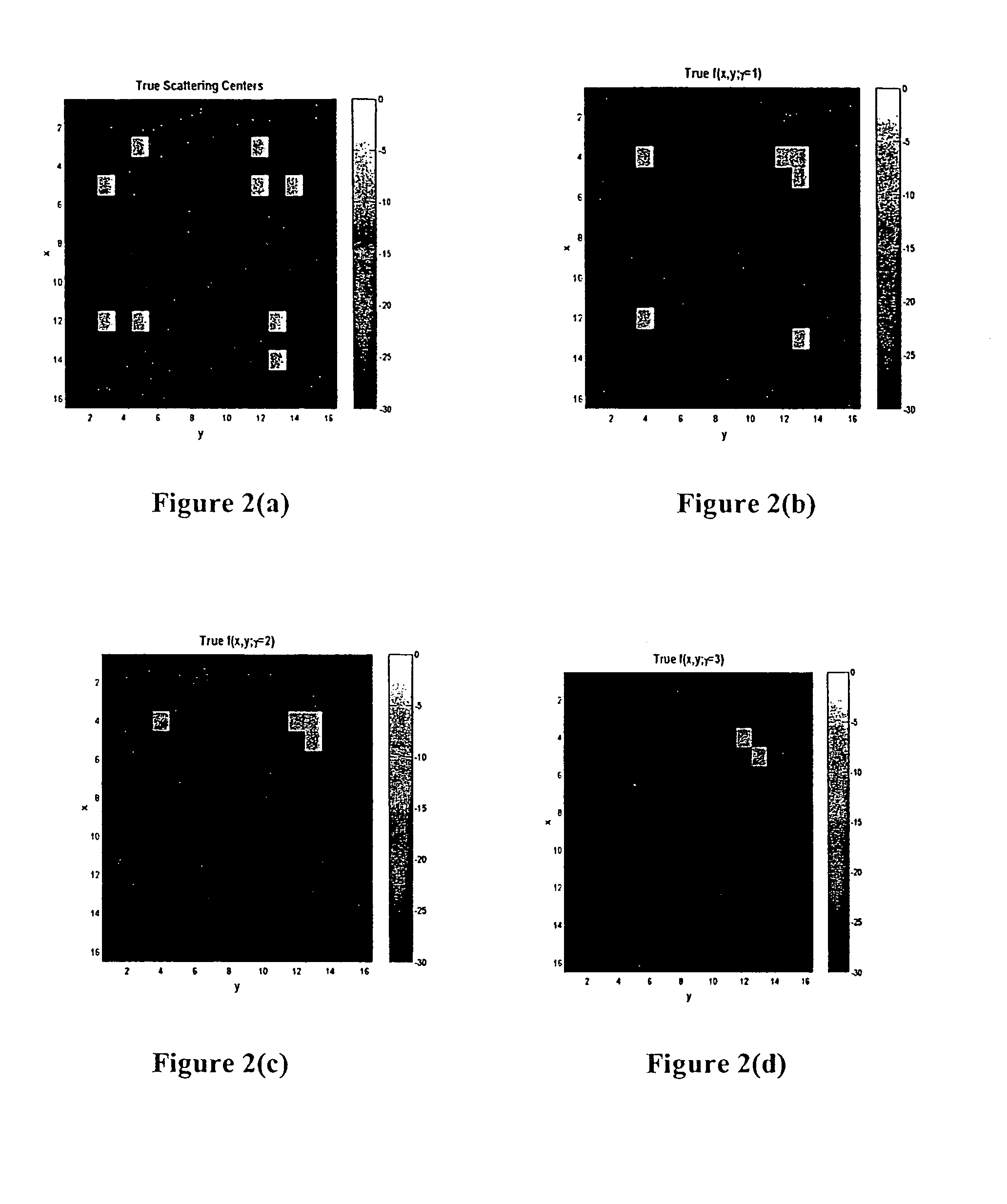
[0013]Described herein are frequency-domain back-projection processes for forming, e.g., spotlight SAR images that are not corrupted by the effects of multiple-bounce ghosting artifacts. These processes give an approximately exact reconstruction of the multiple bounce reflectivity function (MBRF) ƒ(x,y,γ). As shown in the embodiments herein, the reconstruction process is not affected to any greater extent by noise and interference than in the case of the single bounce processing. Specifically, the evaluation of ƒ(x,y,γ) in the γ=0 plane gives an approximately exact reconstruction of the true object scattering centers which is uncorrupted by multiple-bounce contributions to the phase history data G(ξ, θ). In addition, the non-zero dependence of ƒ(x,y,γ) upon the MB coordinate γ can be used to facilitate the identification of features-interest within the imaged region.
[0014]In an embodiment of the present invention, a process is described for incorporating the effects of multiple bounces obtained using the back projection imaging process referred to herein, in order to obtain a cleaned up image that has removed the misleading effects of the multiple bounces, commonly referred to as multiple bounce ghosts

Problems solved by technology

A particular imaging scenario wherein the prior art process is insufficient includes determining the physical distribution of the scattering centers for cases in which multiple-bounce echoes occur.
For example, prior art processes would have a difficult time determining from three (3) received echoes that instead of three scattering centers for an object-of-interest, the image actually contained two targets, wherein the third echo was between the two scattering

Method used


Image

  • Method for developing and using an image reconstruction algorithm for multipath scattering
  • Method for developing and using an image reconstruction algorithm for multipath scattering
  • Method for developing and using an image reconstruction algorithm for multipath scattering

Examples


Embodiment Construction

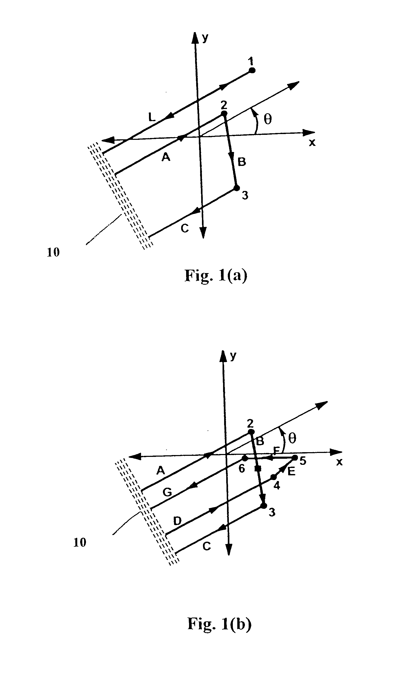
[0044]In a preferred embodiment of the present invention, the imaging process assumes the condition that a scattered waveform has the same characteristics as the incident waveform. In the context of SAR imaging, the measured range to target (i.e., assumed object-of-interest) of a given multiple bounce (MB) scattering event at some aperture angle is identical to that of an equivalent single bounce (SB) scattering event. FIG. 1a presents an example of such equivalent scattering events. In this example, the transmitter is co-located with the receiver (both shown as 10) at a large distance from the region-of-interest, so that the effects of a curved wave front can be neglected. One skilled in the art recognizes that the process described herein may be adjusted for non co-located transmitter and receiver configurations, as well as for distances from the region of interest which result in curved wavefronts. Additionally, multiple receivers may be used in order to introduce additional degr...


PUM


Abstract

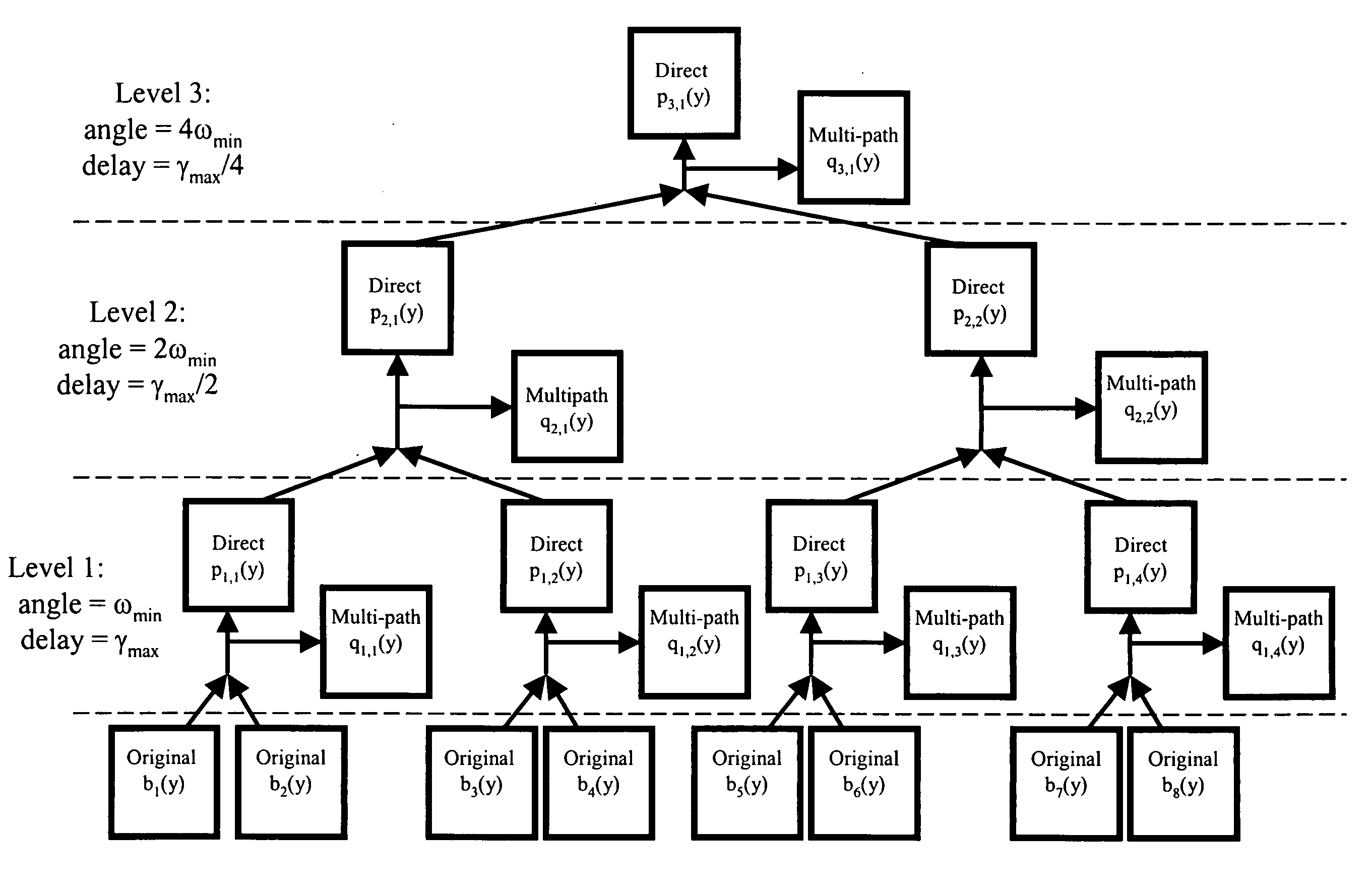
Described herein is an implementation of the IRAMS processing based upon a multi-delay-resolution framework applied to SAR image data measured at different aspect angles. The power of this new embodiment of IRAMS is that it produces a good separation of immediate response scatterer and delayed response scatterer data for the case of anisotropic scattering events, i.e., those in which the scattering intensity depends upon the aspect angle. Two sources of delayed response scattering include multiple reflection scattering events and delayed responses arising from the physical material composition of the scatterer. That is, this multi-delay-resolution IRAMS processing separates immediate response and delayed response scattering for cases in which there exist delayed response scattering data in the original SAR image data at some aspect angles, but the intensity of these delayed response scattering data is weak or non-existent at different aspect angles. Thus, this IRAMS embodiment provides the additional information of the particular aspect angles at which delayed response scattering effects are most important, thereby improving both the estimates of the delayed response scattering data and the immediate response scattering data.

Description

CROSS-REFERENCE TO RELATED APPLICATIONS[0001]This application is a continuation-in-part of and claims priority to U.S. patent application Ser. No. 10 / 954,218 entitled “PROCESS FOR MAPPING MULTIPLE-BOUNCE GHOSTING ARTIFACTS FROM RADAR IMAGING DATA” filed Oct. 1, 2004, now U.S. Pat. No. 7,173,562, which is a continuation of U.S. patent application Ser. No. 10 / 631,712 entitled PROCESS FOR MAPPING MULTIPLE-BOUNCE GHOSTING ARTIFACTS FROM RADAR IMAGING DATA”, which 1 Aug. 2003, now U.S. Pat. No. 6,812,886, which claims priority to U.S. Pat. No. 6,646,593 similarly titled, which claims priority to U.S. Provisional Patent Application No. 60 / 345,639, entitled “SPOTLIGHT SAR IMAGE FORMATION WITHOUT MULTIPLE-BOUNCE GHOSTING ARTIFACTS” filed Jan. 8, 2002, all of which are incorporated herein by reference in their entireties.[0002]Embodiments of the invention may have been conceived or first actually reduced to practice in the performance of work under a Government contract. As a result, the Gov...

Claims


Application Information

Patent Timeline
IPC IPC(8): G01S13/89G01S13/00G01S13/90
CPCG01S13/003G01S13/9035G01S13/9027G01S13/9017G01S13/9052
Inventor GARREN, DAVID ALANGREENO, ROBERT R.
Owner LEIDOS
Why Eureka
Try Eureka