
Methods and systems for optimising the design of aerodynamic surfaces

Active Publication Date: 2011-06-30
AIRBUS OPERATIONS SL
View PDF9 Cites 8 Cited by
  • Summary
  • Abstract
  • Description
  • Claims
  • Application Information

AI Technical Summary

Benefits of technology

[0016]Another object of this invention is to provide methods and systems which will permit the designer of the aerodynamic surfaces to visualise, together with the surface geometry, the relevant aerodynamic characteristics thereof.
[0017]Another object of this invention is to provide methods and systems which will permit reduction in the costs of aerodynamic surface design.
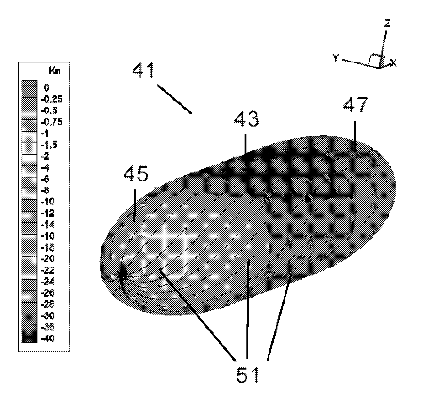
[0025]In a preferred embodiment of the invention, the graphic representation of said variable is carried out on the actual surface of the body (through for example, the use of colour codes). As a result it is possible to facilitate particular zones appropriate for optimisation.

Problems solved by technology

This leads to greater cost and duration of the design processes.

Method used


Image

  • Methods and systems for optimising the design of aerodynamic surfaces
  • Methods and systems for optimising the design of aerodynamic surfaces
  • Methods and systems for optimising the design of aerodynamic surfaces

Examples


first embodiment

[0056]In the invention illustrated in FIGS. 3 and 4, the curvature values are represented on the actual surface of the body 41 by means of a pre-established colour code.

second embodiment

[0057]In the invention illustrated in FIGS. 5 and 6, the curvature values are represented on flow lines 51 by means of a pre-established colour code.

[0058]Furthermore, the values of the curvature may be represented along a specific flow line as shown in FIGS. 7 and 8 in which the evolution of the normal curvature is represented with the coordinate X for the flow line 53 (formally, the maximum information would be obtained by using the actual parameter arc of the flow line considered as a viewing coordinate, however, the example used is sufficient for our purposes, being less complex). In FIG. 8 in the zone of the curvature leap between cylinder 43 and semi-ellipsoids 45, 47 the ordinates have been amplified so that they can be better appreciated.

[0059]It should be noted that the normal maximum curvature of the cylinder takes the value 1 / R that is, 10 m̂(−1) which is that observed by the parallels, whereas the minimum is 0, which is that appearing in the meridians (which generate the...


PUM


Abstract

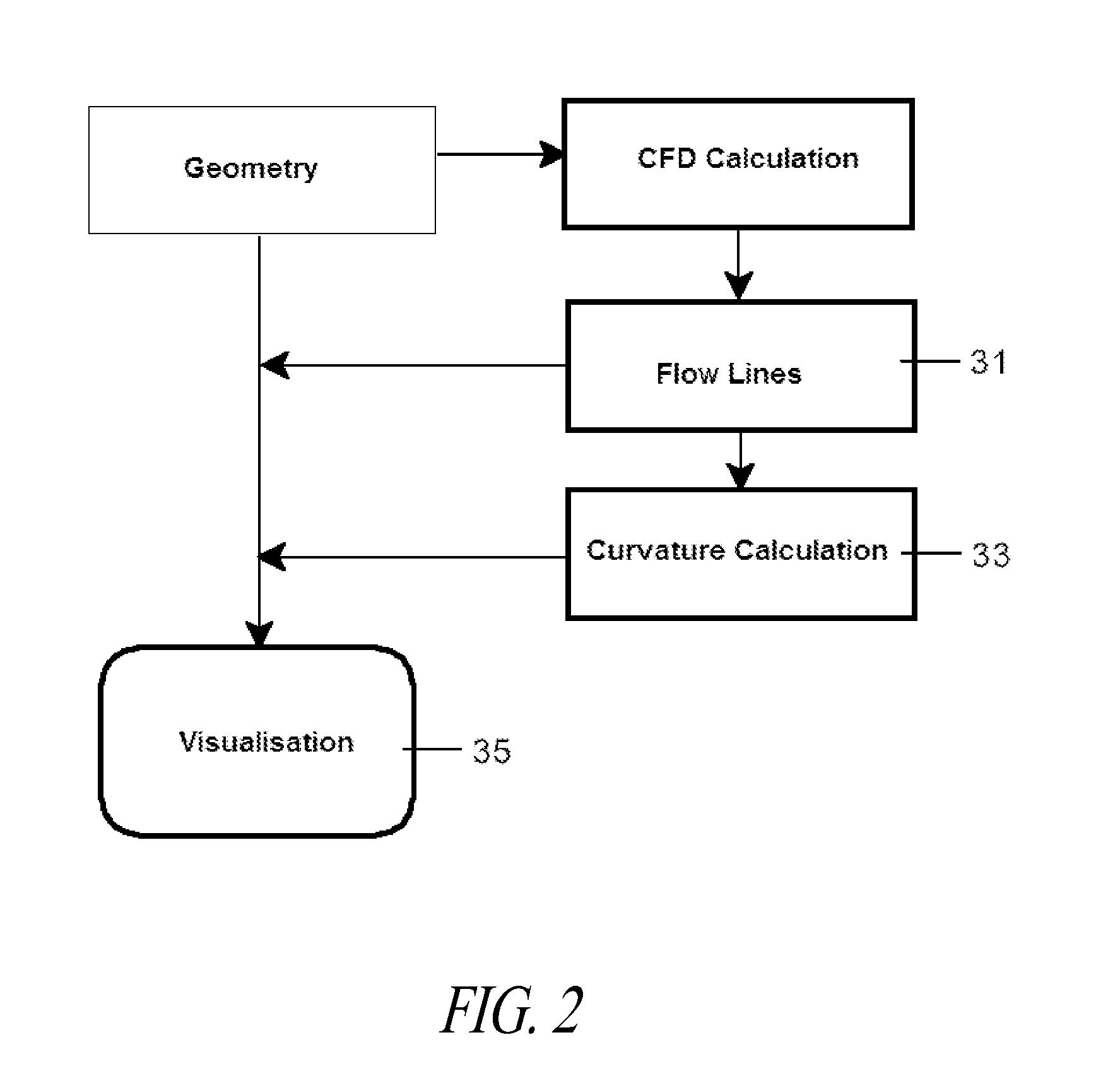
Methods and systems for optimising the design of aerodynamic surfaces. They include in the design process of the aerodynamic surface of a body (41) which moves through a flow field, the following steps: a) preparation of a CFD simulation of said body (41); b) resolution of the CFD calculation for specific conditions of the flow field and for obtaining the flow lines (51) of the flow on said surface; c) calculation of at least one geometrical variable of the surface such as the normal curvature, according to the direction of said flow lines (51) and additionally at least one relevant variable of the aerodynamic flow, such as the pressure gradient; d) simultaneous visualisation of the surface of said body (41) and of at least one geometric variable and, additionally, said at least one variable of the aerodynamic flow.

Description

CROSS-REFERENCE TO RELATED APPLICATION[0001]This application claims the benefit under 35 U.S.C. §119(e) of Spanish Patent Application No. ES 200931082, filed Nov. 30, 2009, which application is incorporated herein by reference in its entirety.BACKGROUND[0002]1. Technical Field[0003]This invention refers to methods and systems for optimising the design of the surfaces of bodies moving through a fluid medium, and in particular methods and systems for optimising the design of aircraft surfaces.[0004]2. Description of the Related Art[0005]Currently aircraft design is carried out using computational fluid dynamics (CFD) and wind tunnel testing (WTT) with the current trend being to reduce tunnel testing and increase simulation. The advantages of CFD simulation are significant, as the time needed to obtain a solution is reduced, and more optimised solutions may be obtained due to the flexibility and automation of the process.[0006]A CFD calculation requires a 3D discrete model of the aircr...

Claims


Application Information

Patent Timeline
IPC IPC(8): G06F17/50
CPCG06F17/5018G06F2217/16G06F17/5095G06F2111/10G06F30/23G06F30/15Y02T90/00
Inventor REDONDO GARCIA, DANIELDE BONA PIEDRABUENA, JAVIER
Owner AIRBUS OPERATIONS SL
Learn More