Multilayer torsional hinged mirror with a recessed drive/sensing permanent magnet

a technology of permanent magnets and hinge mirrors, applied in microelectromechanical systems, instruments, optics, etc., can solve problems such as affecting flatness, and achieve the effect of reducing the flexing of the mirror and small siz

Active Publication Date: 2007-08-21
TEXAS INSTR INC
View PDF2 Cites 14 Cited by
  • Summary
  • Abstract
  • Description
  • Claims
  • Application Information

AI Technical Summary

Benefits of technology

[0008]According to another embodiment of the invention, the selected depth of the recess is the same as the selected thickness of the hinge layer. This of course means that the recess forms an aperture completely through the hinge layer. Therefore, according to this embodiment, the permanent magnet is also located in the recess, however, the bottom side of the permanent magnet is mounted or bonded to the back side of the mirror layer. This arrangement has the advantage in that manufacturing magnets of a sufficiently small size presents no serious difficulties. However, forces on the magnet introduce stresses on the mirror plate, which may affect flatness.
[0009]The above described embodiments for mirror assemblies may be used with various types of mirror assemblies, including multilayered mirror assemblies wherein the back side of the mirror layer defines a central spine and a pair of perimeter ridges for reducing the flexing of the mirror. Other embodiments of the mirror assembly may include a hinge plate that also includes central spines and / or perimeter ridges.

Problems solved by technology

However, forces on the magnet introduce stresses on the mirror plate, which may affect flatness.

Method used


Image

  • Multilayer torsional hinged mirror with a recessed drive/sensing permanent magnet
  • Multilayer torsional hinged mirror with a recessed drive/sensing permanent magnet
  • Multilayer torsional hinged mirror with a recessed drive/sensing permanent magnet

Examples


Embodiment Construction

[0017]The making and using of the presently preferred embodiments are discussed in detail below. It should be appreciated, however, that the present invention provides many applicable inventive concepts that can be embodied in a wide variety of specific contexts. The specific embodiments discussed are merely illustrative of specific ways to make and use the invention, and do not limit the scope of the invention.

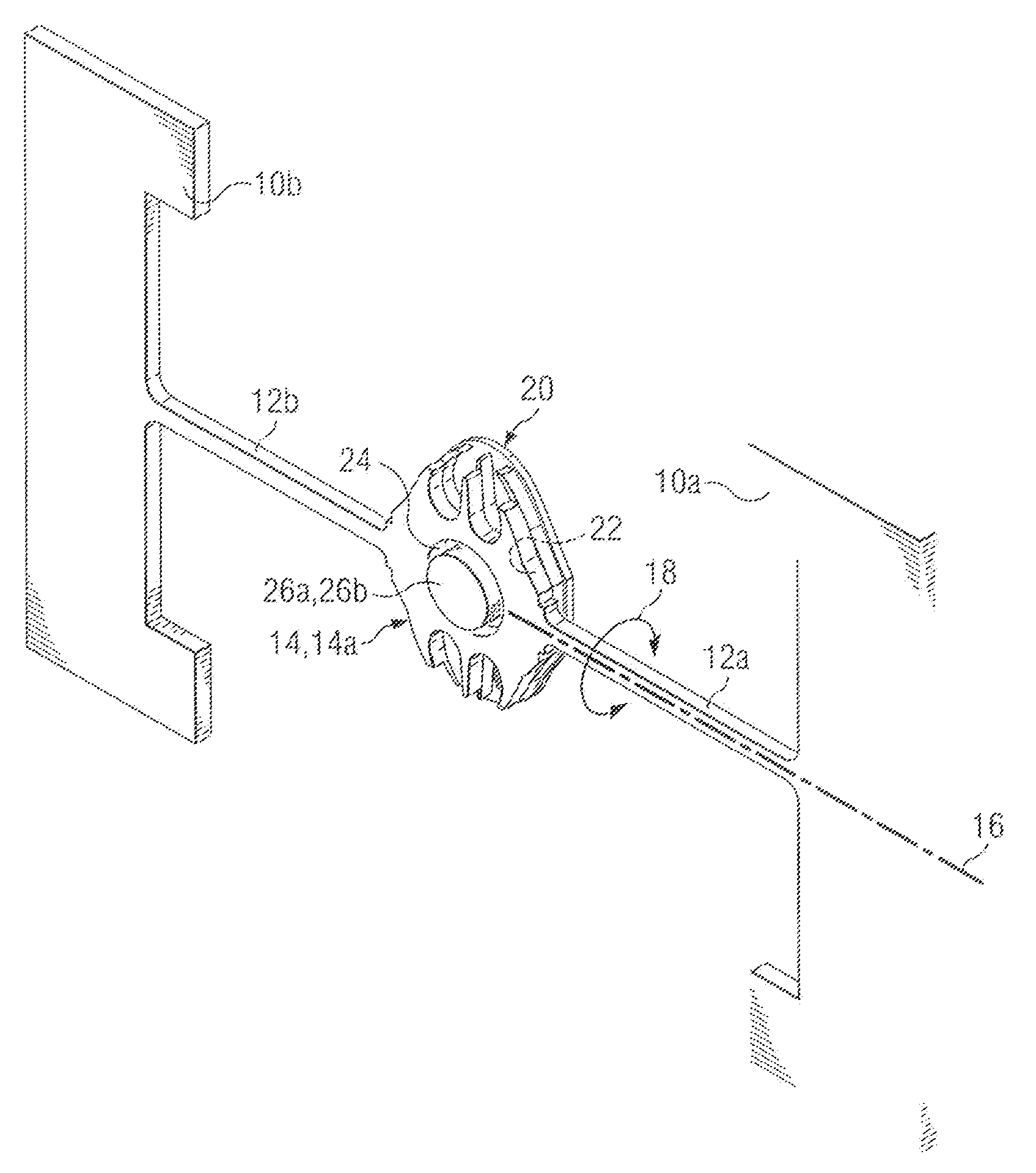
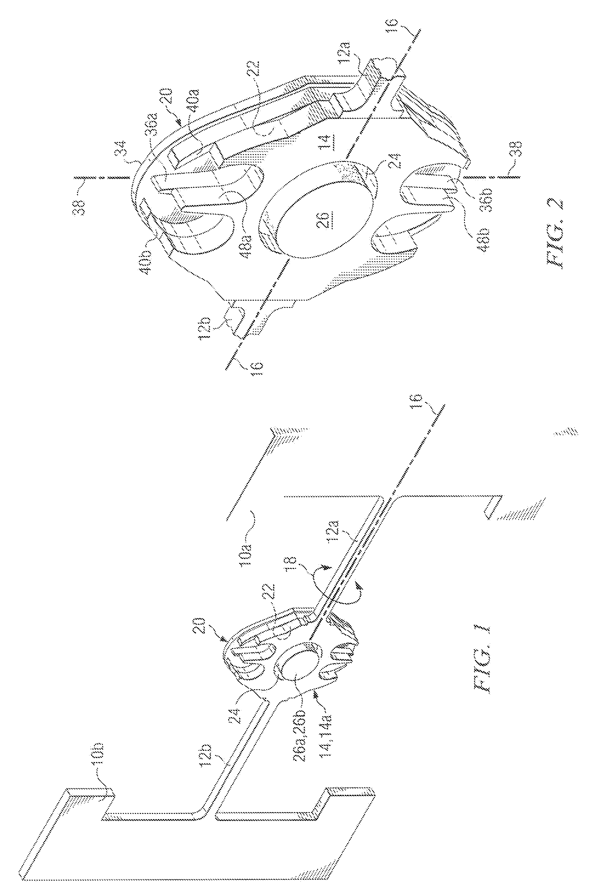
[0018]Referring now to FIG. 1, there is shown a perspective view of an embodiment of the present invention. As shown, the mirror assembly includes a pair of anchor plates 10a and 10b that support a pair of torsional hinges 12a and 12b. The torsional hinges in turn support a hinge plate 14 (14a). As will be appreciated by those skilled in the art, the mirror assembly may be designed to readily resonate at a selected frequency as it oscillates or pivots back and forth around its torsional hinges 12a and 12b, which lie along pivoting axis 16. The rotational motion is indicated b...


PUM


Abstract

A multilayered torsional hinged mirror assembly that includes a drive / sensing permanent magnet. To allow for permanent magnets having increased thicknesses, a hinge plate of the mirror defines a recess for receiving the permanent magnet. The recess may be etched completely through the hinge plate such that the permanent magnet is bonded to the back side of the mirror layer, or alternately may extend part way through the hinge plate to allow the permanent magnet to be mounted to the bottom of the recess. In both embodiments, the center of mass of the mirror assembly can be adjusted to lie on the pivoting axis of the mirror assembly by selection of the depth of the recess and the shape and mass of the permanent magnet.

Description

CROSS-REFERENCE TO RELATED APPLICATIONS[0001]This application claims the benefit of U.S. Provisional Application No. 60 / 556,121, filed on Mar. 24,2004; and is a Continuation-In-Part of U.S. application Ser. No. 10 / 681,934 filed on Oct. 9, 2003, now U.S. Pat. No. 6,956,684, which claims benefit to Provisional Application No. 60 / 424,915, filed on Nov. 8, 2002; and is a Continuation-In-Part of U.S. application Ser. No. 10 / 682,015 filed on Oct. 9, 2003, now U.S. Pat. No. 6,999,215, which claims benefit to Provisional Application No. 60 / 424,915, filed on Nov. 8, 2002. Each of these applications is hereby incorporated herein by reference.[0002]This application relates to the following co-pending and commonly assigned patent applications: Ser. No. 11 / 055,392, filed concurrently herewith, entitled A Torsional Hinged Mirror Assembly With Central Spines And Perimeter Ridges To Reduce Flexing; and Ser. No. 11 / 066,834, filed Feb. 24, 2005, entitled A Single Piece Torsional Hinted Device With Ce...

Claims


Application Information

Patent Timeline
Patent Type & Authority Patents(United States)
IPC IPC(8): G02B26/08
CPCB81B3/007G02B26/0833G02B26/085G02B26/0858G02B26/105B81B2201/042
Inventor ORCUTT, JOHN W.
Owner TEXAS INSTR INC
Why Eureka
Try Eureka