Recording/playback device

a recording/playback device and recording technology, applied in the field of recording/playback devices, can solve the problems of user discomfort and inability to control the switching timing, and achieve the effect of preventing adverse effects caused during catching-up playback

Inactive Publication Date: 2007-08-21
PANASONIC CORP
View PDF6 Cites 5 Cited by
  • Summary
  • Abstract
  • Description
  • Claims
  • Application Information

AI Technical Summary

Benefits of technology

[0015]An object of the present invention is to provide a recording / playback device that can prevent adverse effects caused during catching-up playback by dropout of sound information at an instant when the output is switched from catching-up playback to real time live broadcast.

Problems solved by technology

However, the above-described conventional recording / playback device has the following problems.
Moreover, the user cannot control over a switching timing.
Therefore, when a switch is made while an actor is speaking his lines, for example, these lines cannot be completely output, thereby making the user feel uncomfortable. FIG. 13 depicts a state where dropout of sound information at a switching timing (at the time of around 75 minutes from the start of the program) occurs.

Method used


Image

  • Recording/playback device
  • Recording/playback device
  • Recording/playback device

Examples


first embodiment

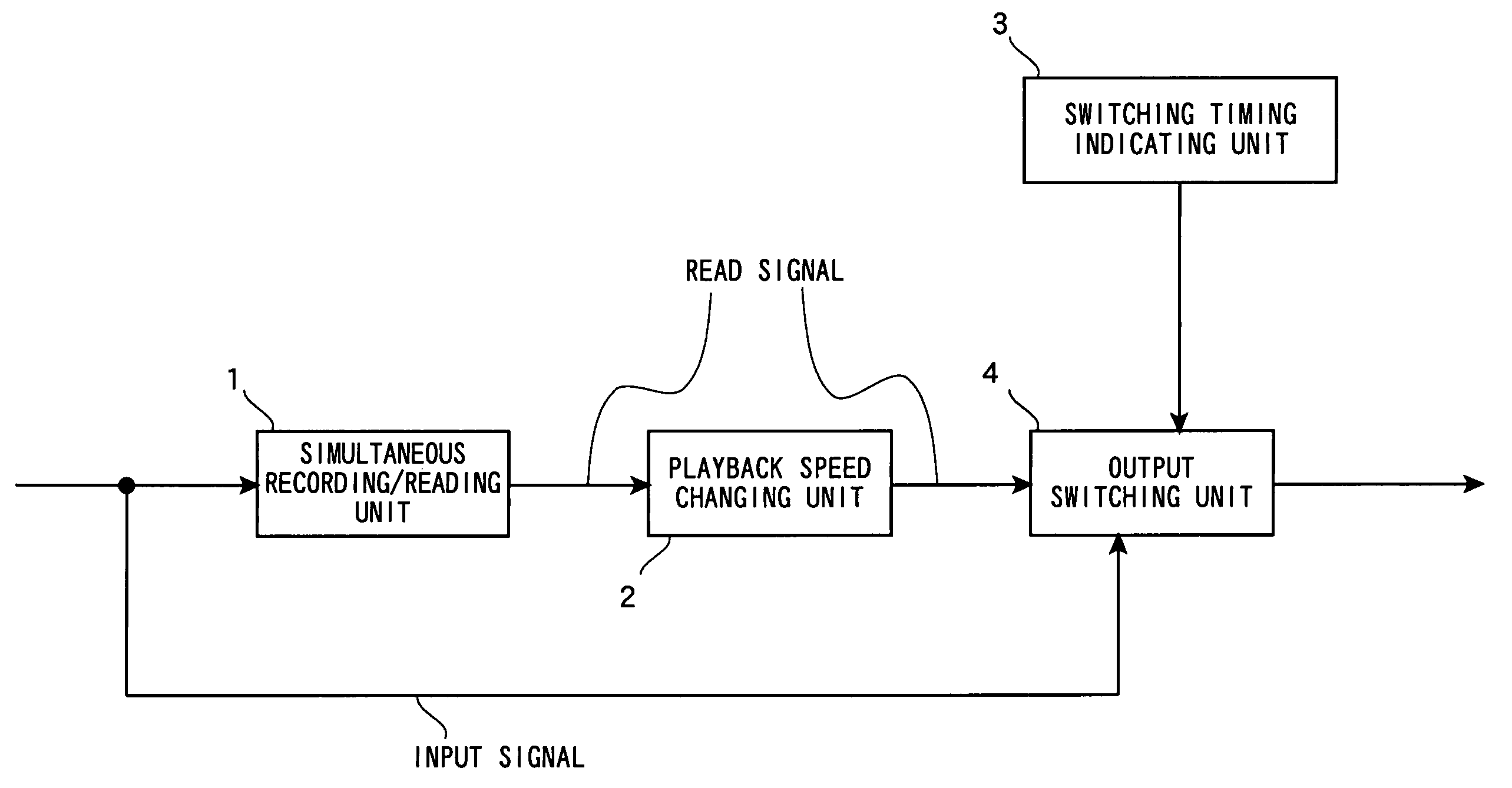
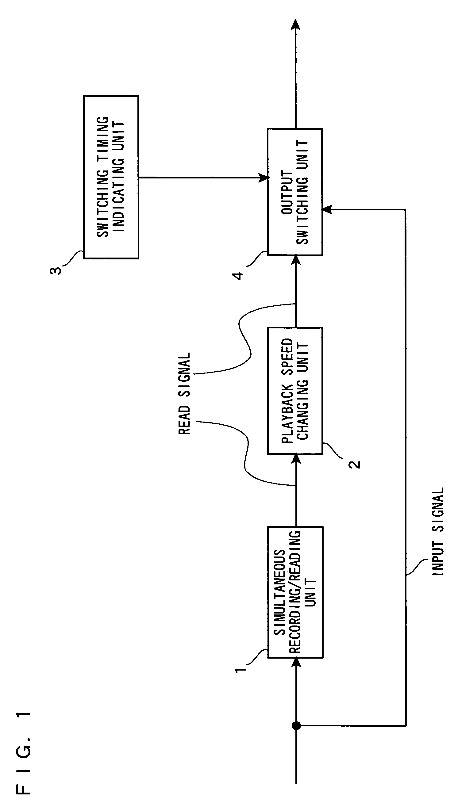
[0043]With reference to FIGS. 1 through 5, a recording / playback device according to a first embodiment of the present invention is described below. FIG. 1 is a block diagram showing the structure of the recording / playback device according to the first embodiment. In FIG. 1, the recording / playback device includes a simultaneous recording / reading unit 1, a playback speed changing unit 2, a switching timing indicating unit 3, and an output switching unit 4.

[0044]The simultaneous recording / reading unit 1 simultaneously records an input signal in a storage device and reads a signal from the storage device. Also, the simultaneous recording / reading unit 1 outputs a difference in the time domain between the input signal and the read signal. Here, the input signal is a signal directly received by a tuner or the like. The input signal may be a signal, such as a television broadcast signal, composed of moving pictures and sounds, or may be a signal, such as a radio broadcast signal, composed o...

second embodiment

[0057]Next, with reference to FIG. 6, a recording / playback device according to a second embodiment of the present invention is described below. In FIG. 6, a switching timing indicating unit 3 is equivalent to the switching timing indicating unit 3 described with reference to FIG. 1 in the first embodiment provided with a commercial message (CM) segment detecting section 12. The other components are identical to those in the first embodiment. Therefore, the same components are provided with the same reference numerals, and are not described in detail herein.

[0058]In FIG. 6, the CM segment detecting section 12 analyzes the input signal (real time live broadcast) to detect whether broadcast is currently in a CM segment. Here, for example, the CM segment detecting section 12 uses a CM segment detecting scheme in which audio stereo broadcast and audio monaural or bilingual broadcast are detected and, when stereo broadcast is partially inserted, the inserted portion is determined as a CM ...

third embodiment

[0061]With reference to FIG. 8, a recording / playback device according to a third embodiment of the present invention is described below. FIG. 8 is an illustration showing one example of the recording / playback device according to the third embodiment. In FIG. 8, a switching timing indicating unit 3 is equivalent to the switching timing indicating unit 3 described in the second embodiment with reference to FIG. 6 with the CM segment detecting section 12 being replaced by a soundless segment detecting section 13. The other components are identical to those in the second embodiment. Therefore, the same components are provided with the same reference numerals, and are not described in detail herein.

[0062]In FIG. 8, the soundless segment detecting section 13 analyzes the input signal to detect whether broadcast is currently in a soundless segment. Here, to detect a soundless segment, a sound detecting scheme using a normal sound power level can be taken. In such a scheme, a sound power le...


PUM

PropertyMeasurementUnit
playback speedaaaaaaaaaa
delay timeaaaaaaaaaa
speedaaaaaaaaaa

Abstract

In simultaneous stream recording and playback, after playback catches up with real time live broadcast, a playback speed changing unit 2 smoothly changes a playback speed to single speed. Nevertheless, an output switching unit 4 continues to perform single-speed playback. During single-speed playback, a switching timing indicating unit 3 indicates a timing of switching to real time live broadcast to the output switching unit 4. Upon receiving the indication from the switching timing indicating unit 3, the output switching unit 4 switches its output to real time live broadcast. With this, in the case of catching-up playback, it is possible to prevent adverse effects caused by dropout of sound information at an instant when the output is changed from catching-up playback to real time live broadcast.

Description

BACKGROUND OF THE INVENTION[0001]1. Field of the Invention[0002]The present invention relates to recording / playback devices and, more specifically, to a recording / playback device having a function of simultaneously recording and reproducing television broadcast signals and audio broadcast signals.[0003]2. Description of the Background Art[0004]Conventionally, recording / playback devices for simultaneously recording and playing back television broadcast streams or audio broadcast streams have utilized either one or both of two types of program playback schemes: chasing playback and catching-up playback. Chasing playback simply allows simultaneous recording and playback. For example, when a user gets back home in the course of preprogrammed recording and desires to watch the program being recorded, the program is played back from the beginning at single speed without a wait for the end of recording but with recording being continued. On the other hand, catching-up playback allows fast-...

Claims


Application Information

Patent Timeline
Patent Type & Authority Patents(United States)
IPC IPC(8): G11B15/02G11B5/09H04N5/76H04N5/781H04N5/85H04N9/804
CPCH04N5/76H04N5/781H04N5/85H04N9/8042
Inventor KAWAMURA, TAKASHI
Owner PANASONIC CORP
Why Eureka
Try Eureka