Optical pulses emitter

a technology of optical pulses and emitters, which is applied in the direction of semiconductor lasers, laser details, electrical apparatus, etc., can solve the problems of small environmental changes, narrow tuning range of dfb laser diodes, and limited tunable wavelength bands

Active Publication Date: 2007-08-21
THE HONG KONG POLYTECHNIC UNIV
View PDF4 Cites 16 Cited by
  • Summary
  • Abstract
  • Description
  • Claims
  • Application Information

AI Technical Summary

Benefits of technology

[0006]Therefore, it is an object of the present invention to provide an improved apparatus for relatively conveniently generating optical pulses primarily of a desired optical wavelength, which wavelength can be continuously tunable over a wavelength band, or at least provide the public with a useful choice.SUMMARY OF THE INVENTION

Problems solved by technology

However, its stability is liable to small environmental changes, especially when a long laser cavity is involved.
However the DFB laser diode has very narrow tuning range, in other words, the tunable wavelength band is limited, typically less than 2 nm.
In addition, both the fiber laser and the DFB laser diode are expensive, which may not be desirable.
However, owing to the cavity structure of the FP laser diode, conventionally, the tuning of the wavelength of the output short pulses is usually implemented on a mode-to-mode basis, i.e., the smallest wavelength tuning is limited by the mode spacing of the FP laser diode.
This essentially limits the application of the FP laser diode in optical fiber communication in that the mode of the FP laser diode may not coincide with one of the ITU grid wavelengths.
Although a smaller wavelength shift or tuning than the mode spacing of the FP laser diode can be achieved by use of thermal control, such an operation can be affected by mode hopping when a large wavelength tuning range is required.

Method used


Image

  • Optical pulses emitter
  • Optical pulses emitter
  • Optical pulses emitter

Examples


Embodiment Construction

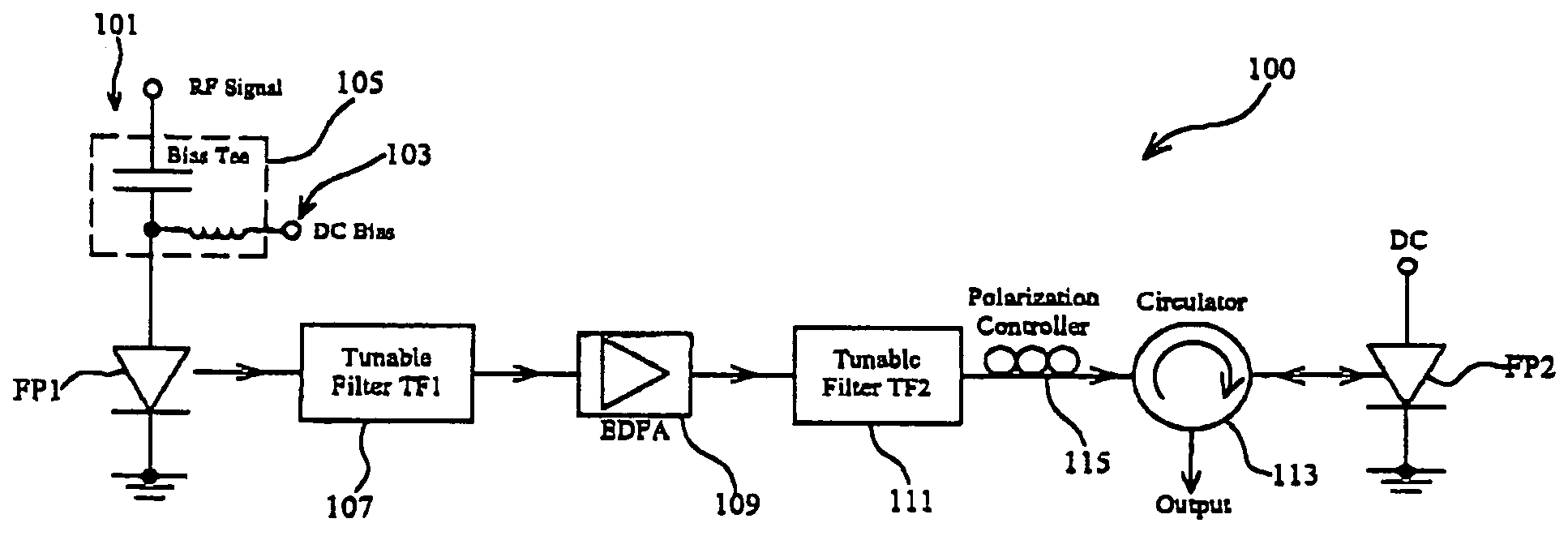
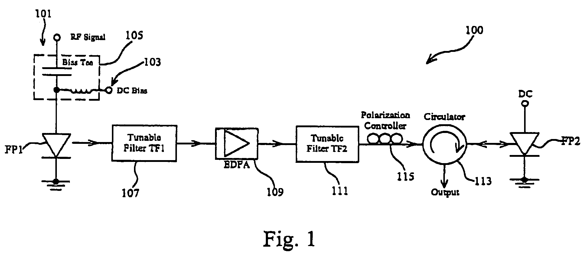
[0029]FIG. 1 illustrates an optical pulses emitter 100 according to an exemplary embodiment of the present invention. In FIG. 1, a first commercial FP laser diode (hereinafter FP1) with a central wavelength of 1537 nm and a threshold current of approximately 15 mA is gain-switched by the use of a radio frequency (RF) electric signal 101 in conjunction with a DC bias current 103 of approximately 14 mA via a bias-tee circuit 105. As generally understood in the art, controlled by the RF signals, FP1 outputs a plurality of optical short pulses over an optical wavelength band the same as its working wavelength band. The RF electrical signal power used to modulate FP1 is approximately 12 dBm.

[0030]The output from FP1, which is a gain-switched FP laser diode and acts as a master source in the exemplary embodiment, is firstly directed to a tunable optical bandpass filter (hereinafter TF1) 107 with a bandwidth of approximately 1 nm before the optical short pulses are power amplified by an er...


PUM


Abstract

An optical pulses emitter includes a first and a second Fabry-Perot laser diodes. The first and second laser diodes have a first and second working optical wavelength band respectively, and the first and second working wavelength bands has at least an overlapped wavelength band. The emitter also includes a signal source in connection with the first laser diode such that a plurality of optical pulses over the first working optical wavelength band is generated and an optical filter for filtering the optical pulses so as to output a plurality of optical pulses primarily of a desired optical wavelength, which falls into the overlapped wavelength band. The emitter further includes an optical amplifier along an optical path between the first and second Fabry-Perot laser diodes for amplifying the optical signals passing therethrough. The optical pulses primarily of the desired optical wavelength are injected into the second laser diode, and the second laser diode, stimulated by the injected optical signals, outputs optical pulses primarily of the desired optical wavelength.

Description

BACKGROUND[0001]1. Field of the Invention[0002]The present invention relates to apparatus for generating optical pulses primarily of a desired optical wavelength, which can be continuously tunable over a wavelength band.[0003]2. Background of the Invention[0004]Various mechanisms have been proposed to generate wavelength-tunable optical short pulses. The light source that can be used for such purpose includes fiber laser and semiconductor laser diode. The fiber laser supports a continuous wavelength tuning in a wide wavelength band and at a high repetition frequency and therefore is one of the favorable choices. However, its stability is liable to small environmental changes, especially when a long laser cavity is involved. Some other conventional designs use the distributed feedback (DFB) laser diode, which exhibits stable laser operation with continuous wavelength tuning capability. However the DFB laser diode has very narrow tuning range, in other words, the tunable wavelength ba...

Claims


Application Information

Patent Timeline
Patent Type & Authority Patents(United States)
IPC IPC(8): H01S3/13
CPCH01S5/50H01S3/0078H01S3/06754H01S3/06766H01S5/005H01S5/0078H01S5/06216H01S5/4006
Inventor WANG, DONGNINGFANG, XIAOHUIJIN, WEI
Owner THE HONG KONG POLYTECHNIC UNIV
Why Eureka
Try Eureka