Lock miter gauge

Inactive Publication Date: 2007-08-28
NEFF LESLIE A
View PDF16 Cites 4 Cited by
  • Summary
  • Abstract
  • Description
  • Claims
  • Application Information

AI Technical Summary

Benefits of technology

[0006]In light of the problems associated with the known methods and apparatus for forming 45° lock miter joints, it is a principal object of the present invention to provide a gauge that divides the thickness of a board in two and permits the transfer of that divided

Problems solved by technology

Obtaining correspondence between the centers of the boards and the lock miter bit is not easy.
Normal set-up of a router table to align the center of a board with the center of a 45° lock miter bi

Method used


Image

  • Lock miter gauge
  • Lock miter gauge
  • Lock miter gauge

Examples


Embodiment Construction

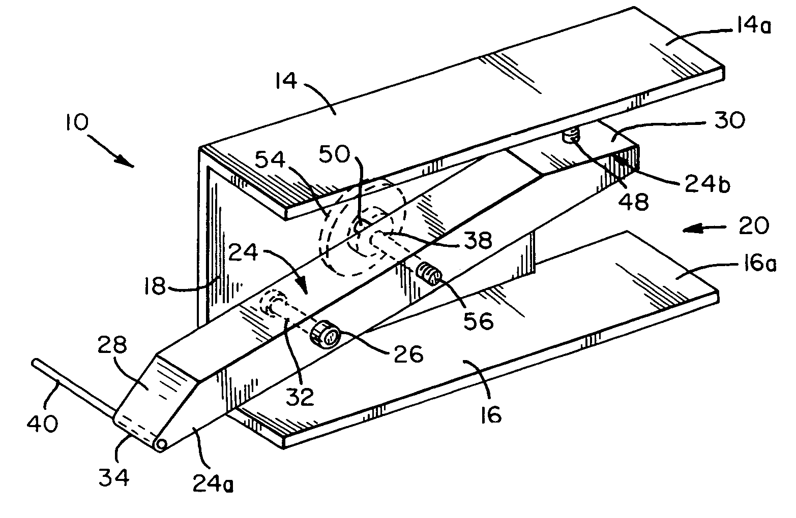
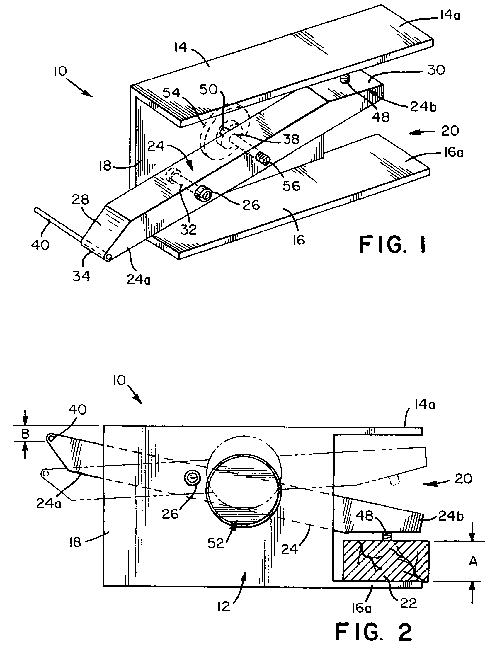
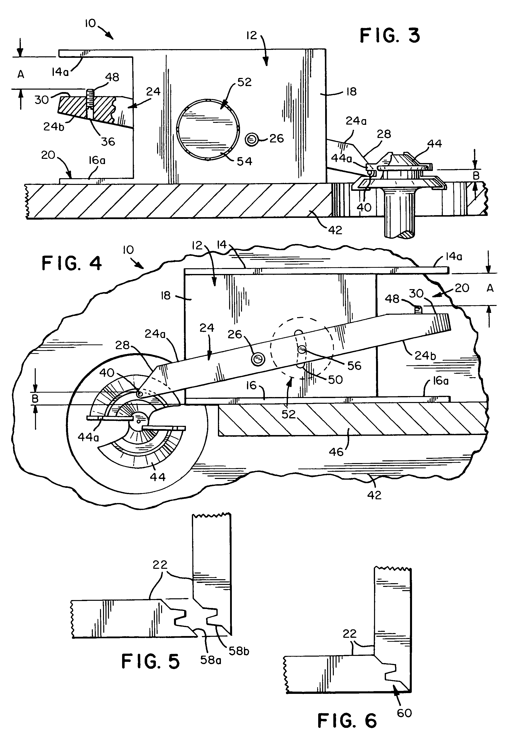
[0020]Referring now to the FIGS., a lock miter gauge in accordance with the present invention is shown at 10. Gauge 10 includes a base 12 having a C-shaped cross-sectional configuration with parallel top and bottom plates 14 and 16 joined along their right sides by a crosspiece 18. Plates 14 and 16 are of equal length and are somewhat longer than crosspiece 18 so as to form rearward projections 14a and 16a that extend rearwardly from crosspiece 18. The space bounded by crosspiece 18 and projections 14a and 16a defines a throat 20 into which one end of a board 22 can be inserted for measuring purposes.

[0021]A gauging arm 24 is pivotally connected to base 12. Arm 24 is positioned between top plate 14 and bottom plate 16 and is connected to crosspiece 18 by means of a pivot pin 26. Arm 24 has a front portion 24a that extends forwardly from pivot pin 26 beyond the front end of base 12. Arm 24 also has a rear portion 24b that extends rearwardly from pivot pin 26 and into throat 20. Front...


PUM


Abstract

A gauge for use by woodworkers in setting the height of a router bit to make lock miter joints with a router table. The gauge includes a base for upright positioning upon a router table. The base has a bottom plate and a top plate connected by a crosspiece. A gauging arm is pivotally connected to the crosspiece at a pivot point and having a front portion extending forwardly from the pivot point and a rear portion extending rearwardly from the pivot point. A gauging finger extends laterally from the front portion of the gauging arm. A setscrew extends upwardly from the rear portion of the gauging arm to a location below the top plate.

Description

FIELD OF THE INVENTION[0001]The present invention relates generally to geometrical instruments and, more particularly, to proportional dividers.BACKGROUND OF THE INVENTION[0002]The 45° lock miter joint is considered by many woodworkers to be one of the most beautiful, yet difficult, to make. Proper tools, like a router table with: a large work surface, a stiff fence, and a powerful motor spinning a sharp lock miter bit, are a necessity. Furthermore, boards being worked must be flat and well prepared to prevent exit tear-out and chipping. Finally, a high degree of skill in adjusting the height and depth of cut of the lock miter bit is needed since a lock miter cut must be made in a single pass.[0003]A careful examination of the two boards joined together by a well-made 45° lock miter joint indicates that the bit that produced the cuts in the boards must have been perfectly centered between the top and bottom surfaces of each of the boards. Of course, the center of a 45° lock miter bi...

Claims


Application Information

Patent Timeline
IPC IPC(8): B23Q17/22
CPCB27C5/10
Inventor NEFF, LESLIE A.
Owner NEFF LESLIE A
Why Eureka
Try Eureka