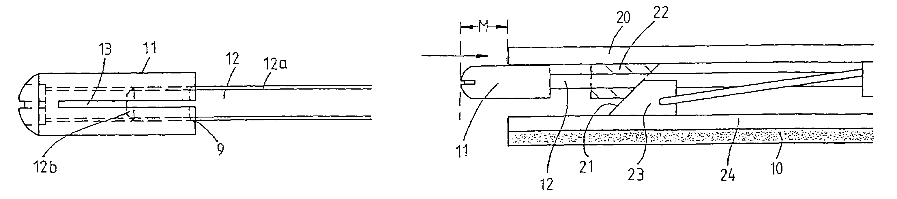
[0009]The method according to the invention for installing and adjusting the door seal device has a considerably greater benefit for the user as compared with the conventional procedure. The previously complicated and time-consuming adjustment of the seal following installation, in which, as a rule, multiple correction of the adjustment initially made was necessary, is dispensed with. The door seal device is, for example, supplied by the manufacturer in a delivered state in which the trigger has an extent of the projection, which is greater than the extent necessary in the application. By means of the mechanism for self-adjustment according to the invention, the first time the door is closed, the self-adjustment of the trigger is then achieved, in which the latter is displaced axially with respect to a transmission element connected thereto to such an extent that the floor
contact pressure of the seal profile is minimized and the result is an optimum adjustment of the seal device. This optimum adjustment is provided when the floor joint is tight but no pressure is exerted on the floor by the seal profile. With this adjustment, when the door is closed, the smallest dragging movement of the seal profile on the floor is obtained. As distinct from the prior art, the adjustment of the position of the trigger takes place automatically and permanently. This means that, during the renewed opening of the door, the trigger remains in the adjusted and thus optimized position, so that, when the door is closed again, no more overloading of the seal profile and of the mechanism occurs. The extent of the projection of the trigger is therefore reduced automatically according to the invention and is maintained during all subsequent door-closing operations. However, if the conditions change as a result of external conditions, for example because the door sinks, as a result of which the floor clearance of the door seal becomes smaller, the pressure on the trigger increases. In the solution according to the invention, this then leads to automatic readjustment, that is renewed displacement of the axial position of the trigger, as a result of which an optimized adjusted position of the trigger matched to the individual force conditions is then again achieved. This projection position of the trigger, which has arisen as a result of readjustment, is also “permanent”, which, within the context of the present invention, is understood to mean that the trigger remains in the adjusted position even when the door is reopened and does not move back into an earlier position before the adjustment. During all the subsequent closing operations of the door, the trigger therefore covers a shorter displacement travel than before the adjustment.
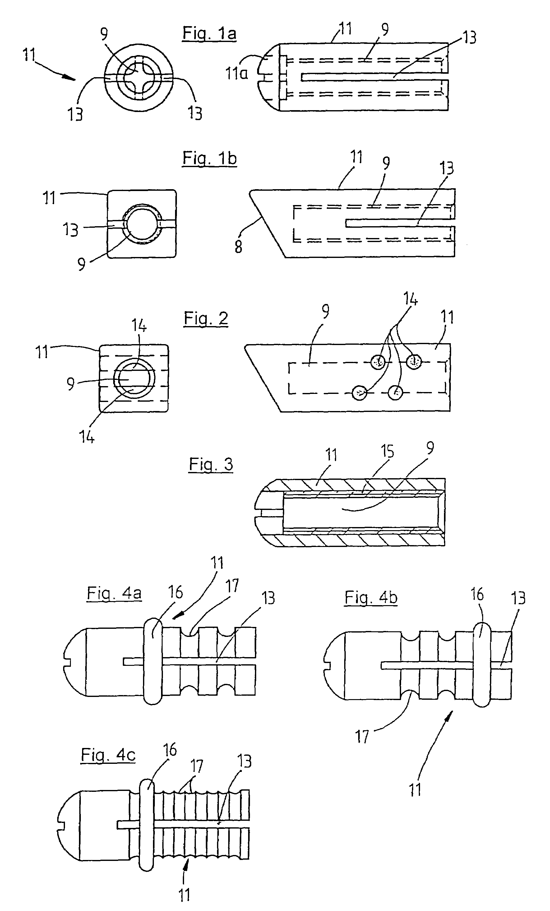
[0010]However, within the scope of the present invention, numerous variants are possible in order to achieve the aforementioned self-adjustment of the trigger. For example, the trigger can be provided with means, which permit occasional radial expansion and elastic reverse deformation of the trigger. By means of a thrust force acting in the axial direction, which is transmitted from the lowering mechanism to the trigger, the latter is expanded and, as a result, is displaced with respect to the transmission element connected to the trigger. As a result of the elastic reverse deformation ability of the trigger, the original state can be produced again, so that it is also possible to perform such a self-adjustment of the trigger repeatedly. This is expedient, for example, when subsequent changes in the environment of the installed door seal are made, for example when a new
floor covering is laid, so that the lower door gap is changed. There can also be an
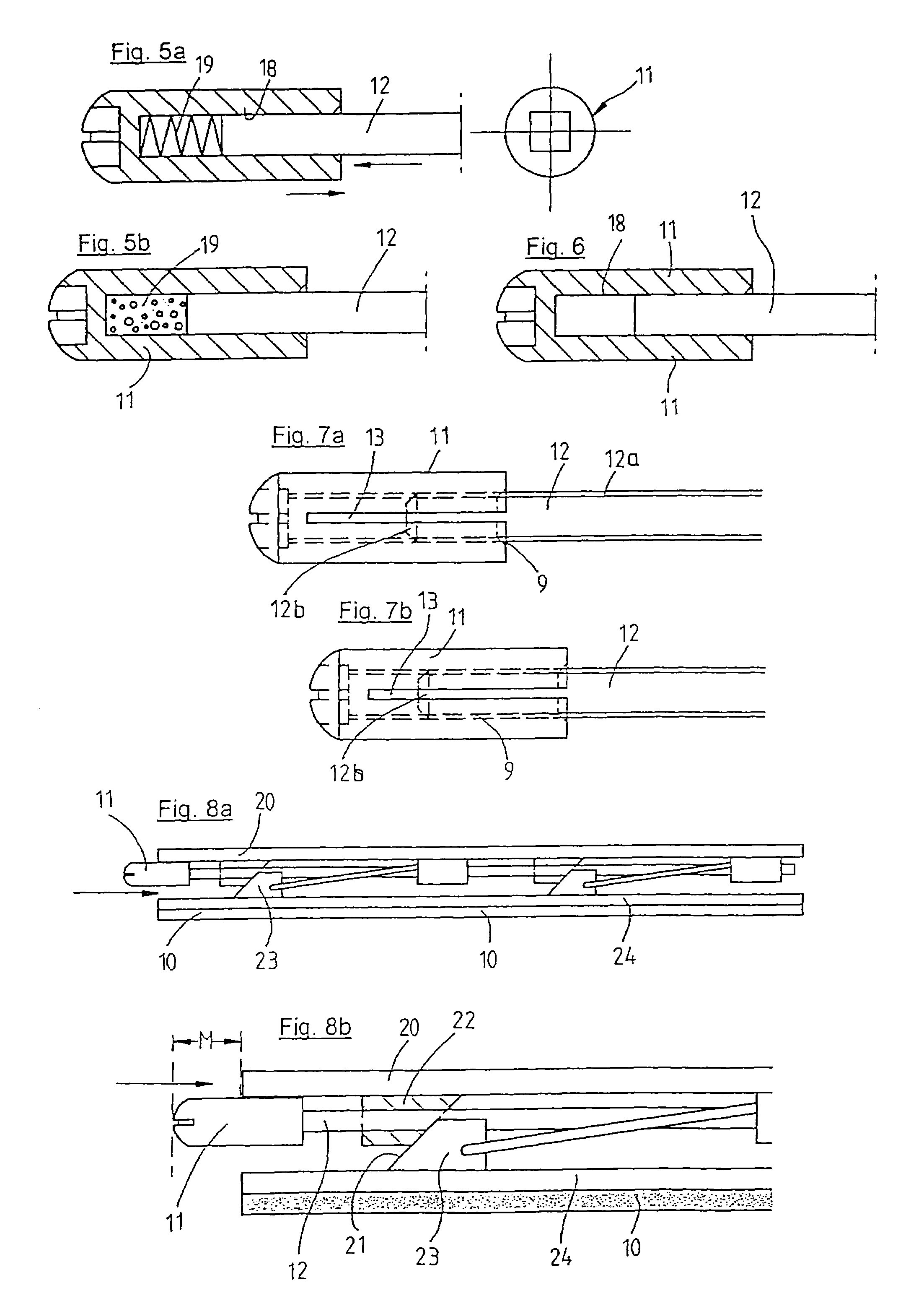
installation error present, for example, which makes it necessary to remove the door seal device again and install it in another door. In this case, according to the invention, renewed self-adjustment of the trigger can likewise be carried out following the renewed installation of the door seal device. During the installation of the door seal device, according to the invention the procedure can be such that, firstly, the trigger is brought into a position in which too high a floor pressure of the seal profile is to be expected. The first time the door is closed, the self-adjustment of the trigger is then carried out, by means of which the latter is moved further inward into the correct position. In this way, it is possible to prevent the situation where, even before the adjustment, a position of the trigger is chosen in which the latter is located too far in, so that self-adjustment would then no longer be possible, since the trigger can naturally adjust itself only in one direction. The aforementioned radial expansion of the trigger during the self-adjustment operation can be achieved, for example, by means of a slit in the wall of the trigger. One possible alternative to a trigger, which jumps over a thread during the self-adjustment, consists, for example, in a plurality of elastic elements provided in an axially mutually offset arrangement being introduced into a bore in the trigger, which accommodates a transmission element. As an alternative to this, the trigger, for example, can be provided in a bore with a rubber thread, at least in some portions, which achieves a similar effect since, when a thrust force occurs, the transmission element slips in the rubber thread until the adjusted position is reached.
[0015]According to one development of the invention, provision can be made that, in addition to the self-adjustment, manually adjustable fine adjustment of the trigger is also possible. This is expedient, for example, when the self-adjustment is carried out in steps which are still too coarse, for example by
jumping over individual threads, so that still more accurate adjustment of the trigger can be carried out manually, which permits intermediate positions between the individual positions of the self-adjustment. In this case, thought should be given to the fact that, as necessitated by the construction, a change in the axial adjustment of the trigger by one length unit can make up a multiple of change on the displacement of the seal device, so that very fine adjustment is practical. However, self-adjustment can also be carried out in such a way that a finely stepped displacement of the trigger becomes possible.

