Feeder cable reduction

a technology of feeder cable and reduction, applied in the field of radio frequency communication, can solve the problems of time-consuming and dangerous maintenance of the masthead, reducing the amount of electronics placed in the masthead, and reducing the number of electronics

Inactive Publication Date: 2005-09-29
APPLE INC
View PDF54 Cites 59 Cited by
  • Summary
  • Abstract
  • Description
  • Claims
  • Application Information

AI Technical Summary

Benefits of technology

[0005] The present invention allows transmission of multiple signals between masthead electronics and base housing electronics in a base station environment. At least some of the received signals from the multiple antennas are translated to being centered about different center frequencies, such that the translated signals may be combined into a composite signal including each of the received signals. The composite signal is then sent over a single feeder cable to base housing electronics, wherein the received signals are separated and processed by transceiver circuitry. Prior to being provided to the transceiver circuitry, those signals that were translated from being centered about one frequency to another may be retranslated to being centered about the original center frequency. In one embodiment, the multiple antennas represent main and diversity antennas. In such an embodiment, the received signals from the diversity antenna(s) may be translated and combined with the signal received from the main antenna. The receive signal from the main antenna may or may not be translated prior to combining with the translated signals from the diversity antenna(s). The present invention is applicable in single mode and multi-mode environments. It is also applicable to systems which use four branch receive diversity. Future systems such as MIMO which may use two transmit signals and four receive signals per sector will also greatly benefit from this invention. In essence this invention can be leveraged in any deployment scenario where there are more receive signals than transmit signals.

Problems solved by technology

Historically, the amount of electronics placed in the masthead has been minimized, due to inhospitable environmental conditions, such as lightning, wind, precipitation, and temperature extremes, along with the difficulty in replacing the electronics when failures occur.
Maintenance of the masthead is time-consuming and dangerous, given the location of the masthead.
Thus, a decade ago the antenna feeder cables were an insignificant cost associated with a base station environment, whereas today the cost of the antenna feeder cables is a significant portion of the cost associated with the base station environment.

Method used


Image

  • Feeder cable reduction
  • Feeder cable reduction
  • Feeder cable reduction

Examples


Embodiment Construction

[0014] The embodiments set forth below represent the necessary information to enable those skilled in the art to practice the invention and illustrate the best mode of practicing the invention. Upon reading the following description in light of the accompanying drawing figures, those skilled in the art will understand the concepts of the invention and will recognize applications of these concepts not particularly addressed herein. It should be understood that these concepts and applications fall within the scope of the disclosure and the accompanying claims.

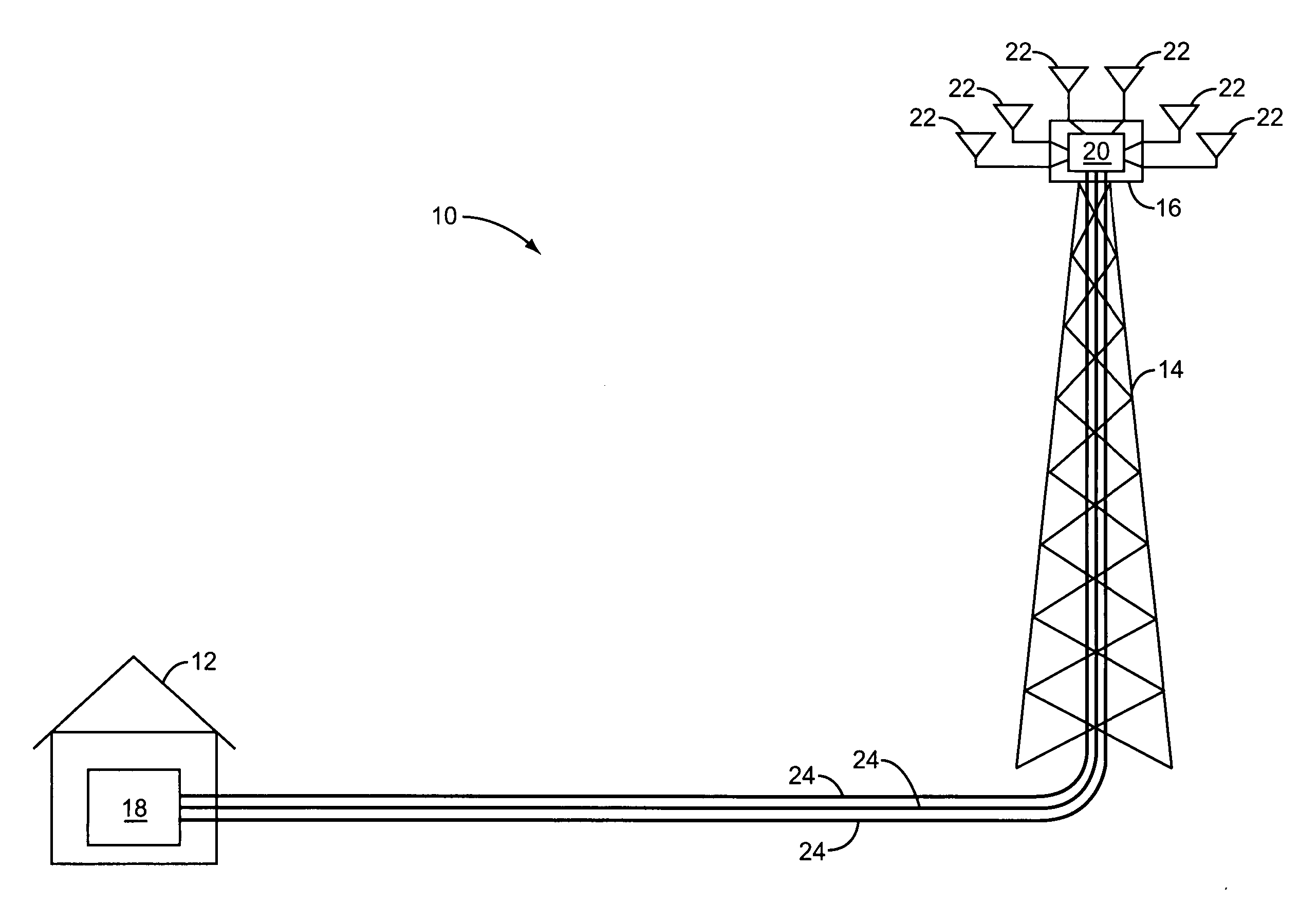
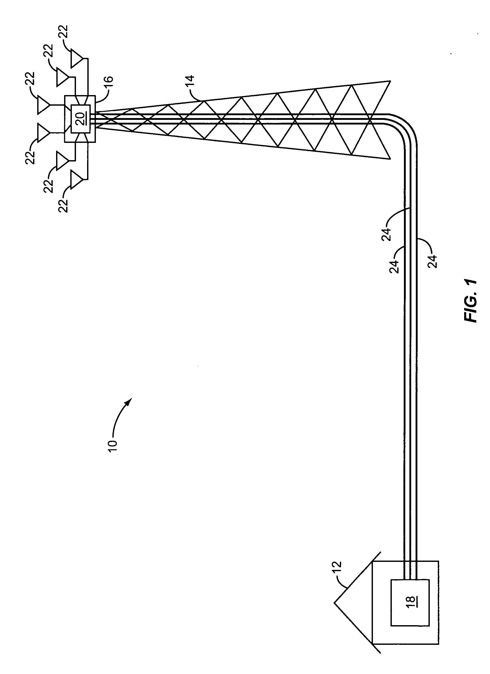
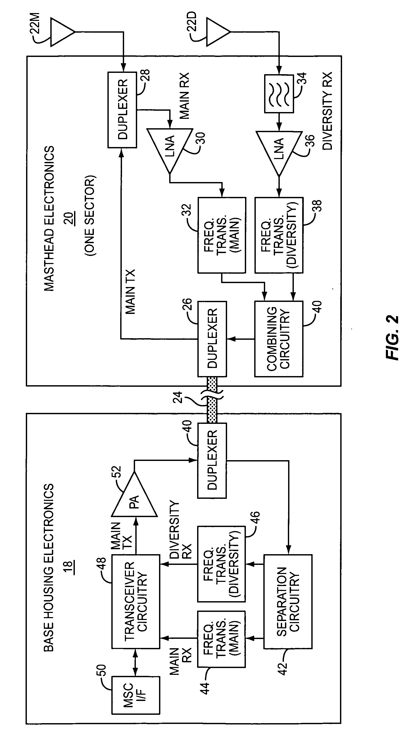
[0015] The present invention facilitates the reduction of cabling required in a base station environment. In general, signals that were normally transmitted over separate cables are frequency shifted about different center frequencies, combined, and sent over a single cable. At a receiving end of the cable, the combined signals are recovered and processed in traditional fashion. The invention is particularly useful in a diversit...


PUM


Abstract

The present invention allows transmission of multiple signals between masthead electronics and base housing electronics in a base station environment. At least some of the received signals from the multiple antennas are translated to being centered about different center frequencies, such that the translated signals may be combined into a composite signal including each of the received signals. The composite signal is then sent over a single feeder cable to base housing electronics, wherein the received signals are separated and processed by transceiver circuitry. Prior to being provided to the transceiver circuitry, those signals that were translated from being centered about one frequency to another may be retranslated to being centered about the original center frequency.

Description

FIELD OF THE INVENTION [0001] The present invention relates to radio frequency communications, and in particular to translating signals received at one frequency from multiple antennas to being centered about different frequencies, and combining these signals for delivery over a common antenna feeder cable. BACKGROUND OF THE INVENTION [0002] In cellular communication environments, the electronics used to facilitate receiving and transmitting signals is distributed between a base housing and a masthead, which is mounted atop a building, tower, or like mast structure. The actual antennas used for transmitting and receiving signals are associated with the masthead. The masthead will generally include basic electronics to couple the antennas to corresponding antenna feeder cables, which connect to transceiver and amplifier electronics located in the base housing. [0003] Historically, the amount of electronics placed in the masthead has been minimized, due to inhospitable environmental c...

Claims


Application Information

Patent Timeline
Patent Type & Authority Applications(United States)
IPC IPC(8): H03C7/02H04B1/02H04B7/02H04B7/08H04J1/08H04W28/04H04W88/08
CPCH01Q1/246H01Q21/30H04W88/085H04W28/04H04B7/08
Inventor BEAUDIN, STEVEEDWARDS, KEITH RUSSELLHU, XIAOYUNDEANE, PETER
Owner APPLE INC
Why Eureka
Try Eureka