Motorized motor vehicle component

a motor vehicle and component technology, applied in the direction of keyhole guards, lock applications, gearing, etc., can solve the problems of low striking noise and “low strength” design of the corresponding mechanical components, and achieve the effect of reducing the structural limitations of implementation and increasing efficiency

Active Publication Date: 2007-08-28
BROSE SCHLIESSSYSTEME GMBH & CO KG
View PDF8 Cites 6 Cited by
  • Summary
  • Abstract
  • Description
  • Claims
  • Application Information

AI Technical Summary

Benefits of technology

[0011]A primary object of this invention is to embody and develop the known motorized motor vehicle component such that the structural limitations for implementation are minimized, with a simultaneous increase in efficiency.
[0014]This additionally provided blocking element, at this point, is engaged in a controlling manner with the first transmission element of the kinematic chain of the gearing, by which the blocking element can be moved to engage the second transmission element of the kinematic chain of the gearing in a blocking manner. Thus, on the one hand, it is possible by suitable selection of the first transmission element to ensure optimum control of the blocking element for reliable and prompt assumption of the blocking position. On the other hand, suitable selection of the second transmission element ensures an optimum blocking action. Generally, it can be considered optimum if the first transmission element is exposed to a comparatively high torque in order to ensure the motion of the blocking element, and if the second transmission element is exposed to a comparatively low torque so that the resulting blocking moment and the resulting blocking force are low. This leads to a low striking noise and the possibility of a “low strength” design of the corresponding mechanical components.
[0015]An optimum design with respect to control and blocking forces is achieved by the pivot axle or axis of rotation of the blocking element being parallel to the pivot axis or axes of rotation of the first and second transmission element. Such a configuration of the control contour leads to optimum lever ratios for a control force which is as high as possible. Alternatively, by making the first transmission element essentially disk-shaped and arranging the control contour on the face as near as possible to the axis of rotation of the first transmission element the arrangement of the stop as far outside as possible on the second transmission element guarantees a low blocking force.

Problems solved by technology

This leads to a low striking noise and the possibility of a “low strength” design of the corresponding mechanical components.

Method used


Image

  • Motorized motor vehicle component
  • Motorized motor vehicle component
  • Motorized motor vehicle component

Examples


Embodiment Construction

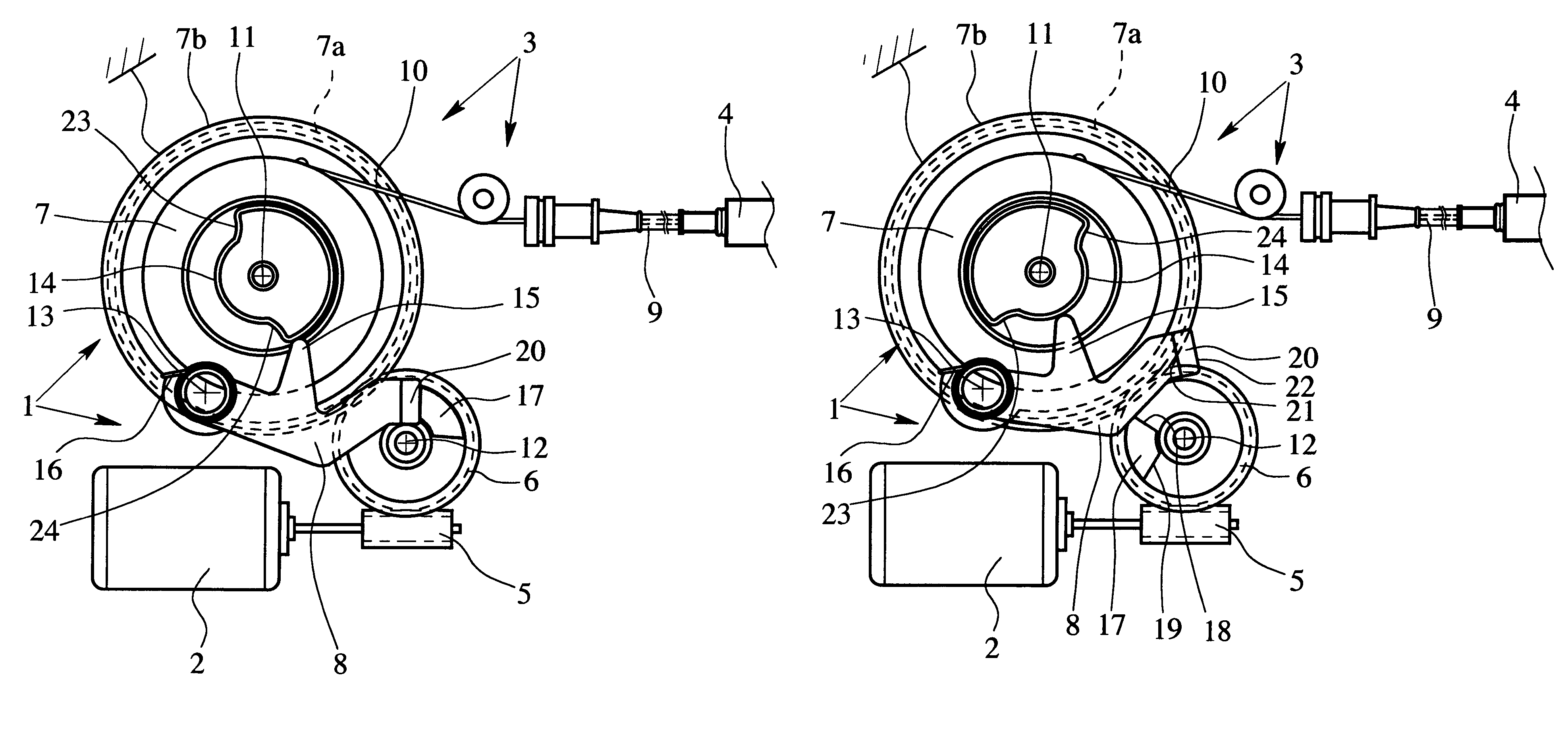
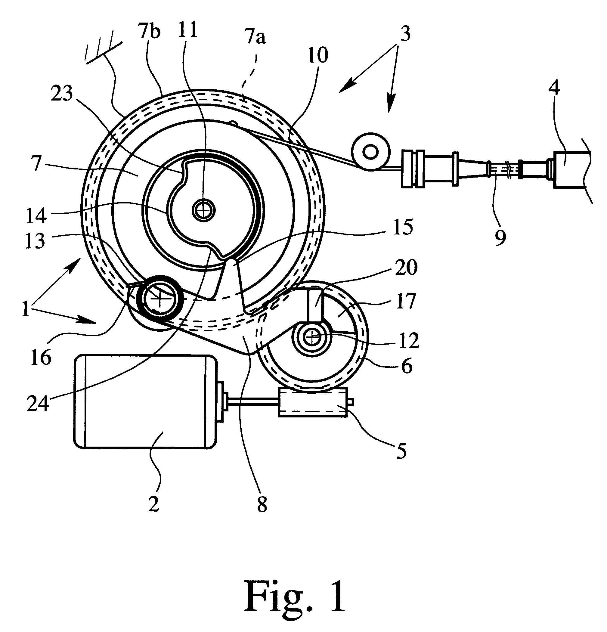
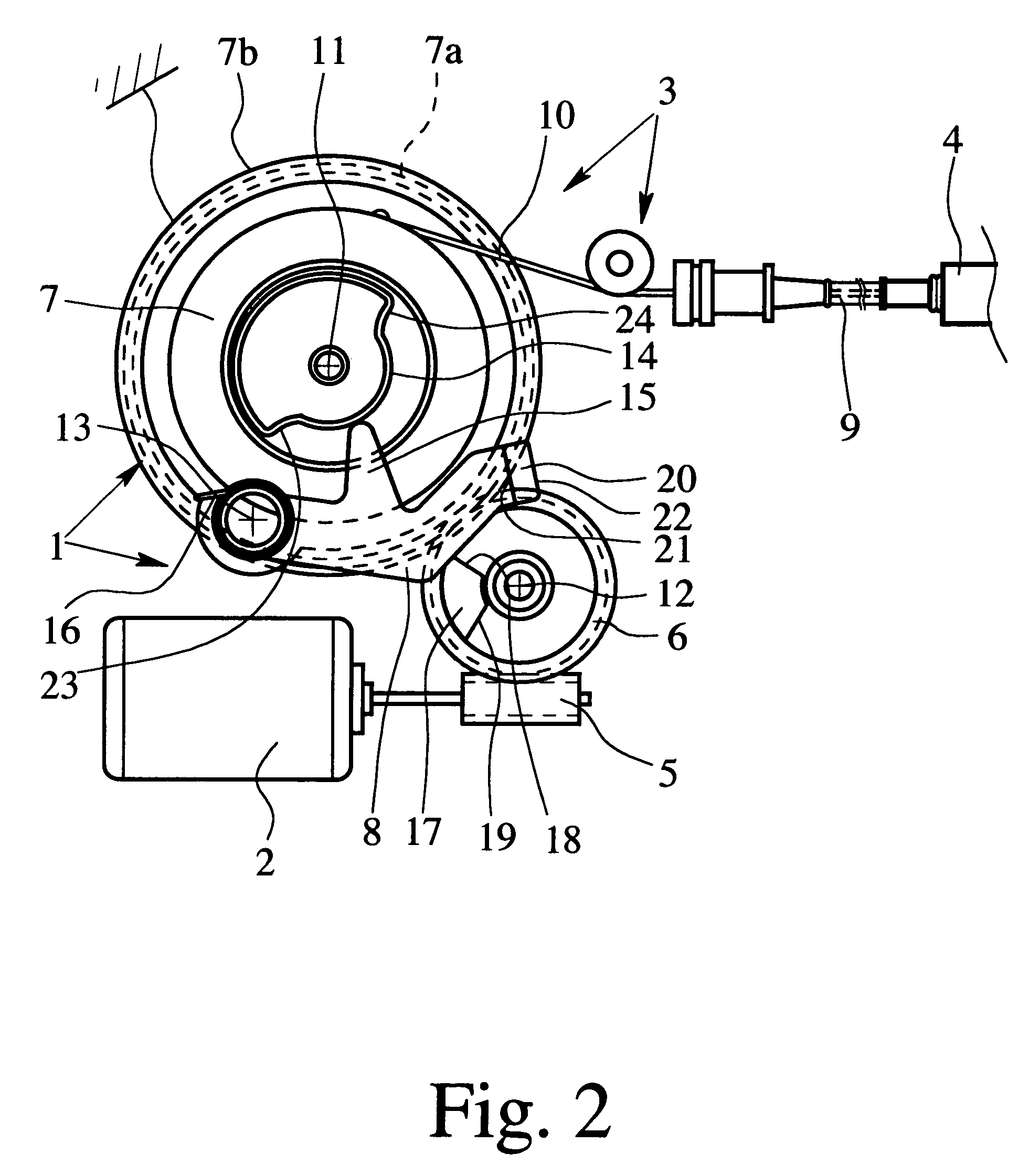
[0025]The motorized motor vehicle component which is shown in FIG. 1 comprises a drive 1 having a motor 2 and gearing 3, and a component 4 which can be moved by means of the drive 1. The gearing 3, as is conventional, has a drive side and a driven side, the motor 2 being coupled by to the driving side of the gearing 3. The driven side of the gearing 3 is coupled to the movable component 4. By linking the motor 2 via the gearing 3 to the movable component 4, the movable component 4 can be driven according to its functionality.

[0026]Depending on which functionality is to be provided by the motor vehicle component, the movable component 4 is a lever, another gear, or the like. Numerous versions of such components are known from the prior art and any of which are contemplated as being usable in accordance with the present invention.

[0027]In this embodiment, the kinematic chain of the gearing 3 runs from the worm 5 which is connected to the motor 2, via the worm wheel 6, then via a sun w...


PUM


Abstract

A motor vehicle component with a drive having a motor, a gearing and a component which is movable by the drive, the motor being coupled to a driving side of the gearing and a driven side of the gearing being coupled to the movable component, a kinematic chain of the gearing between the driving side and the driven side having at least two transmission elements. The drive is operable in blocking operation by a displaceable blocking element that is movable into blocking engagement with the drive. The displaceable blocking element is in addition to the drive and the adjustable component, and is engaged in a controlling manner with the first transmission element of the kinematic chain so that, depending on the position of a first transmission element, it can be moved into blocking engagement with a second transmission element of the kinematic chain.

Description

BACKGROUND OF THE INVENTION[0001]1. Field of Invention[0002]This invention relates to a motorized motor vehicle component with a drive having a motor and gearing and with a component which can be moved by means of the drive, the gearing having a drive side and a driven side, the motor being coupled to the driving side of the gearing and the driven side of the gearing being coupled to the movable component, the kinematic chain of the gearing, between the driving side and the driven side, having at least two transmission elements and the drive being operable in a blocking operation, and for this reason, an displaceable blocking element is movable into blocking engagement with the drive.[0003]Here, the expression “motorized motor vehicle component” encompasses all those components of a motor vehicle which provide functions which can be triggered by a motor. Examples of functions which can be triggered by a motor include the central locking system, opening aid, closing aid or the mechan...

Claims


Application Information

Patent Timeline
Patent Type & Authority Patents(United States)
IPC IPC(8): F16H1/16B60N2/02B60N2/16E05B13/00E05B47/00E05B53/00E05B65/12E05B65/36E05F15/00H02K7/06H02K7/102H02K7/116
CPCB60N2/0232E05B81/25E05B81/38H02K7/06H02K7/1166E05B79/20E05Y2900/538E05F15/40B60N2002/0236Y10T74/19828H02K7/102Y10T70/7915Y10T292/1082B60N2/02253B60N2/02246
Inventor KACHOUH, CHECRALLAHKOTHE, MARKUS
Owner BROSE SCHLIESSSYSTEME GMBH & CO KG
Why Eureka
Try Eureka