Systems and methods for measurement optimization

a measurement optimization and optimization technology, applied in the field of measurement optimization systems and methods, can solve the problems of preventing high numerical aperture lenses from being incorporated in many detection systems, affecting affecting the accuracy of information, so as to reduce the impact of vibration on the reliability of information, reduce the cost, and ensure the effect of accuracy

Inactive Publication Date: 2007-08-28
U S GENOMICS INC
View PDF44 Cites 66 Cited by
  • Summary
  • Abstract
  • Description
  • Claims
  • Application Information

AI Technical Summary

Benefits of technology

[0008]The invention provides, in its broadest sense, a system capable of rapid and reliable detection and / or analysis of agents, such as biohazardous agents. The system combines various technologies, including microfluidics and single molecule detection capability. In some embodiments, microfluidic channels and optics are incorporated directly into a chip, such that the optics can be produced in-focus and at a lower cost. Incorporating optics directly into a chip can reduce the impact that vibrations have on the reliability of information produced by the system. Incorporating optics into the chip can also allow numerous detection zones to be placed into a single chip, thus increasing the amount of information that can be derived from a sample in the chip during a given time frame.
[0016]In another embodiment, a solid medium provides a pathway from the microfluidic channel to the concave reflector along which the emission signal can travel without substantial refraction. In one embodiment, the solid medium extends from a wall of the channel to the concave reflector. Still, in one embodiment, a cover slip is adapted to mate with the chip to enclose the channel and the concave reflector is incorporated into the cover slip. In still another embodiment, the solid medium provides a pathway from the microfluidic channel to the illuminator along which the excitation signal can travel without substantial refraction.

Problems solved by technology

Prior art detection systems can have difficulty distinguishing emission signals from noise and / or disturbances within the system.
However, such compound lenses are often expensive and require significant amounts of space within a system.
This prevents such high numerical aperture lenses from being incorporated in many detection systems, particularly where multiple detection zones are desired.
Expensive and space consuming lenses preclude the utilization of multiple detection zones on a single chip in prior art systems.
In this regard, the amount of information that can be obtained from a sample in a given amount of time (i.e., throughput) can be limited in prior art systems.

Method used


Image

  • Systems and methods for measurement optimization
  • Systems and methods for measurement optimization
  • Systems and methods for measurement optimization

Examples


Embodiment Construction

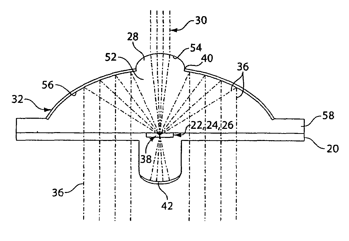
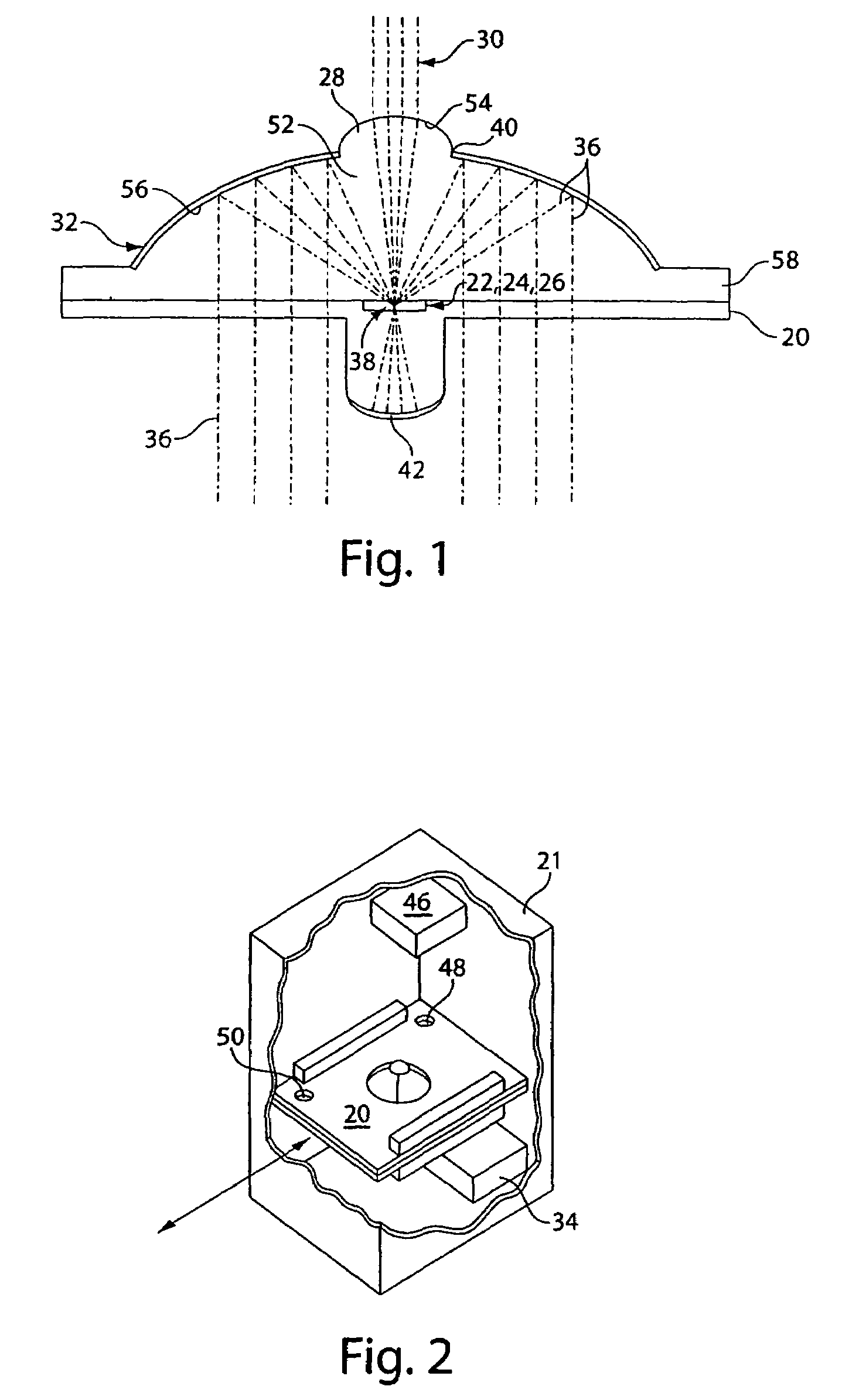
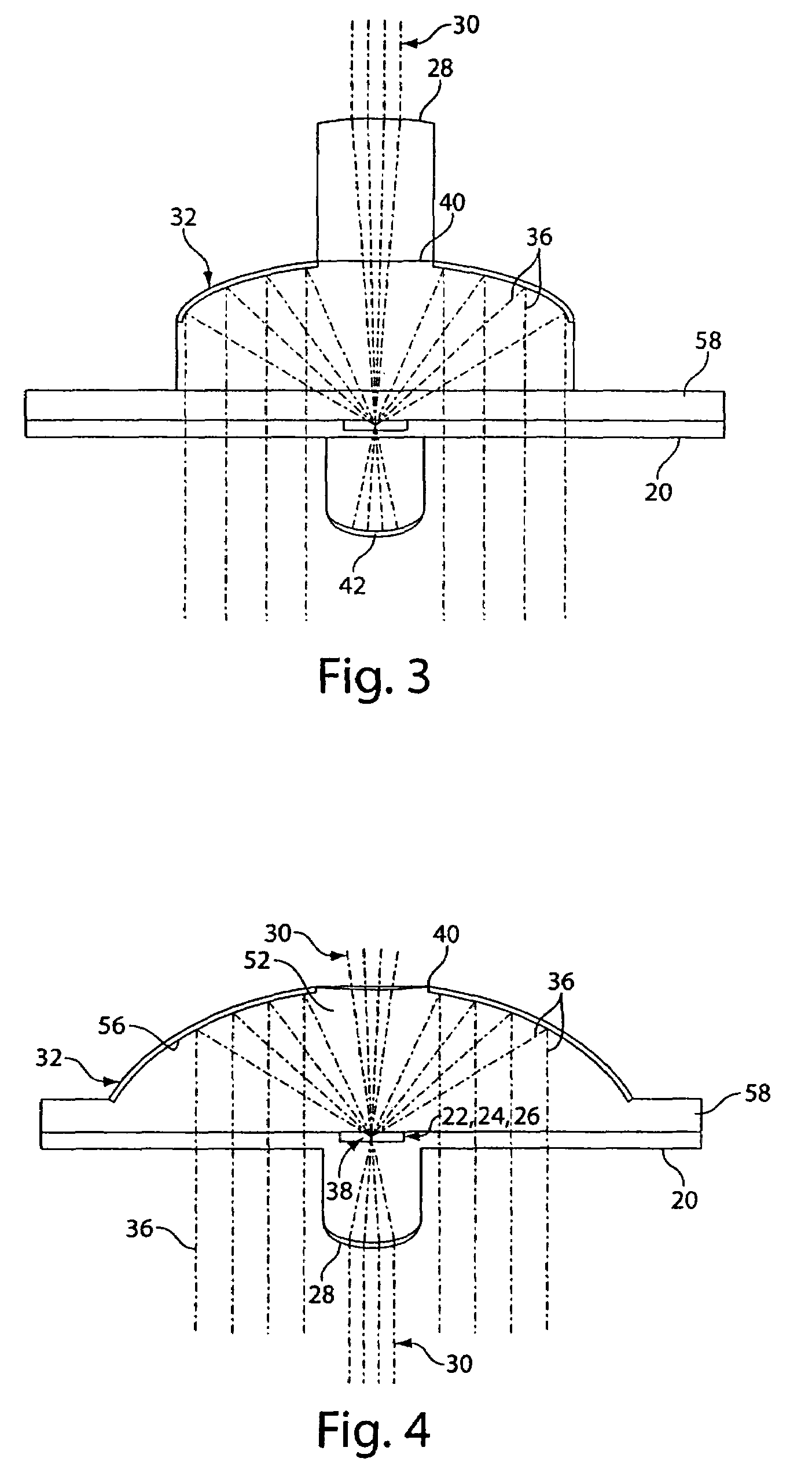
[0040]The invention provides systems and methods for detecting whether an agent is present in a sample. The systems and method generally use chips having microfluidic channels incorporated therein. Optical components are incorporated into the chip to provide various benefits over prior art systems with components that are separate from the chip. In some embodiments, one or more reflectors and / or illuminators are incorporated into the chip during manufacturing to reduce overall system cost. Incorporating illuminators and / or reflectors into the chip can eliminate the need for costly optical components in the system—like adjustable objective lenses. Moreover, incorporating optical components into the chip can make the system less susceptible to vibrations and / or provide a chip that is manufactured in focus. The optical components can be arranged to maximize their numerical aperture and thus improve the signal to noise ratio of emissions received by the system. Still, in some embodiment...


PUM

PropertyMeasurementUnit
collection half angleaaaaaaaaaa

Abstract

The invention relates to methods and systems for detecting and or analyzing an agent in a sample with a chip having optical components incorporated therein.

Description

RELATED APPLICATIONS[0001]This application claims priority to U.S. Provisional Applications Serial No. 60 / 618,453 entitled “Measurement Optimization Using Microlens” filed Oct. 13, 2004, the entire contents of which are incorporated by reference herein.GOVERNMENT SUPPORT[0002]This invention was made in part with government support under Contract No. W81XWH-04-9-0011 from the Homeland Security Advanced Research Projects Agency. The Government may retain certain rights in the invention.FIELD OF THE INVENTION[0003]The invention relates in part to a chip incorporating a microfluidic channel and a lens used to detect contents of the channel.BACKGROUND OF THE INVENTION[0004]Systems are known that utilize chips to receive a sample for optical inspection to determine whether an agent is present in the sample. The agents often include polymers, such as nucleic acids with detachably labeled probes bound thereto in a particular manner. The sample is passed through a detection zone where an exc...

Claims


Application Information

Patent Timeline
Patent Type & Authority Patents(United States)
IPC IPC(8): G01N21/55G01N21/01
CPCB01L3/502715G01N21/05G01N21/6452B01L3/5025B01L2300/0654B01L2300/0816B01L2300/087B01L2300/168B01L2400/0415B01L2400/0487G01N2021/0346G01N2021/058G01N2021/6463G01N2021/6469G01N2021/6478
Inventor LARSON, JONATHAN W.YANTZ, GREGORY R.SEWARD, GEORGEJOHNSON, DAVIDKROGMEIER, JEFFREY R.
Owner U S GENOMICS INC
Why Eureka
Try Eureka