Resolving user-specific narrow beam signals using a known sequence in a wireless communications system with a common pilot channel

a wireless communication system and pilot channel technology, applied in the field of digital radio signal communication, can solve the problems of reducing channel estimation accuracy, user-specific signal more difficult to demodulate, and difficult use of signals,

Inactive Publication Date: 2007-08-28
INTEL CORP
View PDF11 Cites 42 Cited by
  • Summary
  • Abstract
  • Description
  • Claims
  • Application Information

AI Technical Summary

Benefits of technology

[0012]FIG. 3 is a simplified block diagram of a base statio...

Problems solved by technology

However, any difference between signals makes the pilot signal more difficult to use or, in other words, it makes the user-specific signal more difficult to demodulate.
The difference in the propagation channel of the pilo...

Method used


Image

  • Resolving user-specific narrow beam signals using a known sequence in a wireless communications system with a common pilot channel
  • Resolving user-specific narrow beam signals using a known sequence in a wireless communications system with a common pilot channel
  • Resolving user-specific narrow beam signals using a known sequence in a wireless communications system with a common pilot channel

Examples


Embodiment Construction

[0014]Introduction

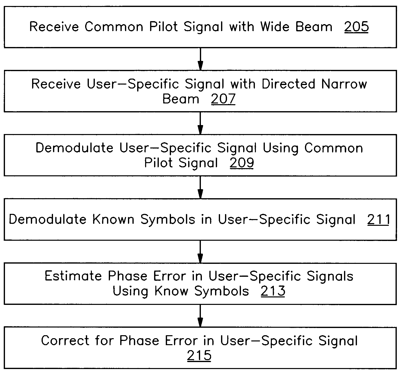
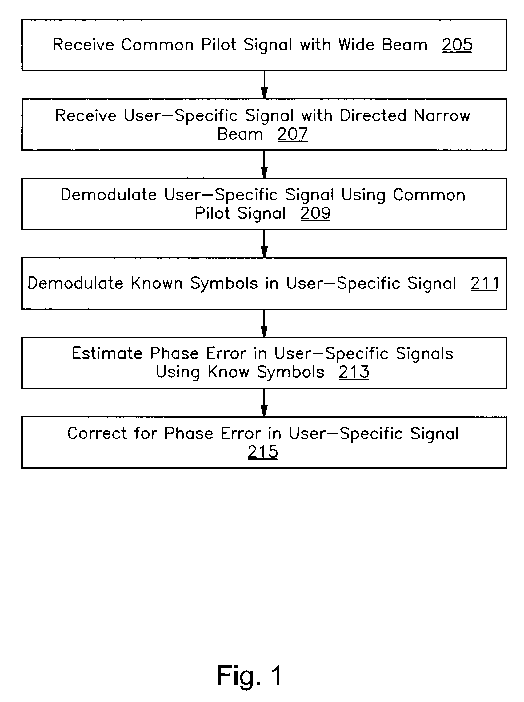
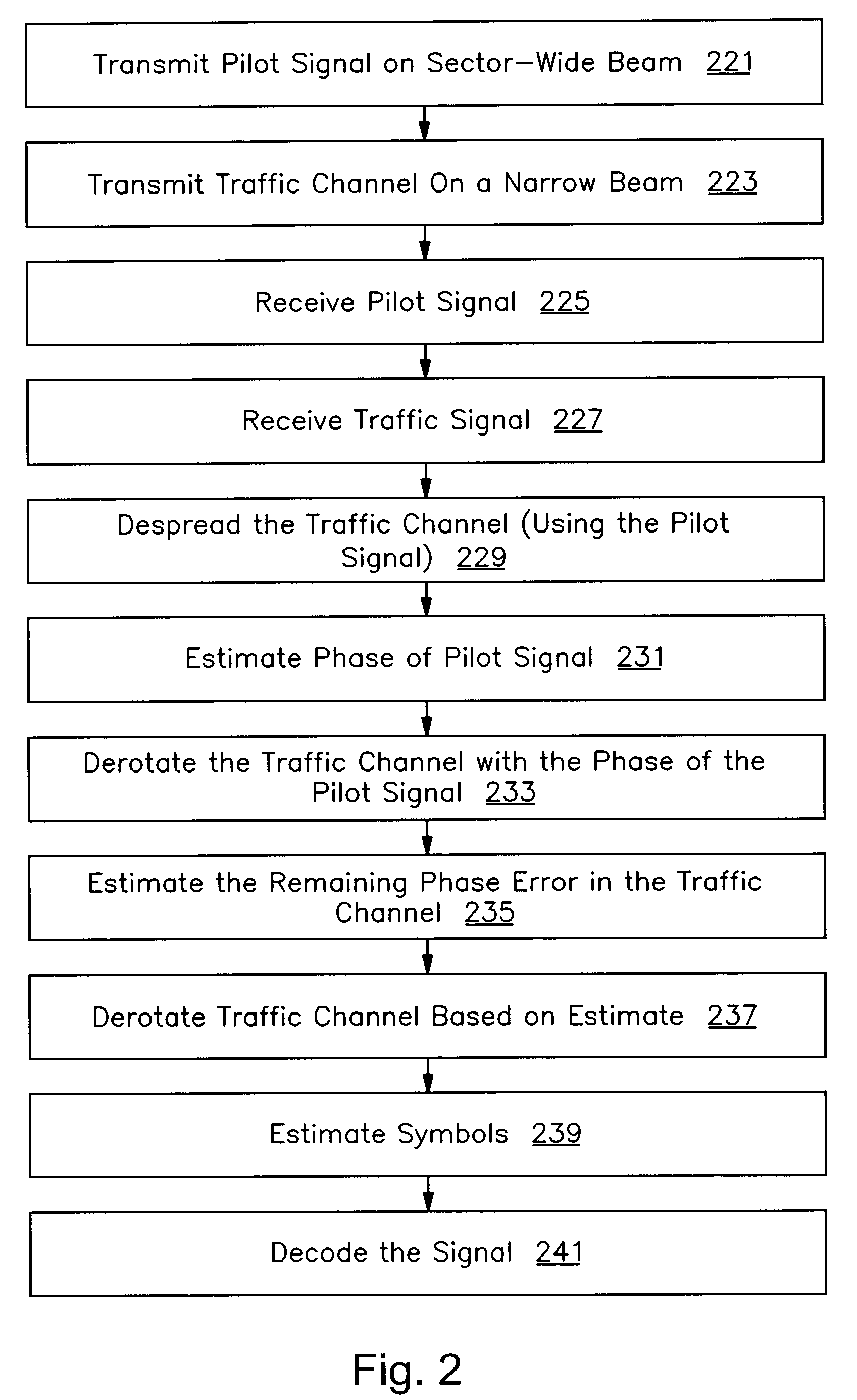
[0015]The channel mismatch between the traffic channel beam and the beam of the pilot channel can be corrected using known symbols in the traffic channel. The user terminal can compensate for the phase error in several different ways. One way is by estimating the phase of the traffic channel constellation and de-rotating it back to the closest constellation point. The estimate can be improved upon by using a small number of known symbols transmitted on the traffic channel to resolve any ambiguity as to which nearest constellation point the signal constellation should be rotated. The phase error compensation can be performed on a per tap basis or after combining the taps in a RAKE receiver. Another way is by re-estimating the traffic channel propagation channel by using the known symbols transmitted by the base station on the traffic channel and using the channel estimated using the sector wide pilot signal.

[0016]Using the channel estimated from the sector wide pilo...


PUM


Abstract

A method and apparatus are provided that corrects for differences in reception between a user-specific signal and a common signal. In one embodiment, the invention includes receiving a common pilot signal transmitted on a wide beam at a remote terminal, receiving a user-specific signal transmitted on a directed narrow beam at the remote terminal, demodulating the user-specific signal using the common pilot signal for channel estimation, estimating a phase error in the demodulated user-specific signal using known symbols in the user-specific signal, and correcting for the phase error in the demodulated user-specific signal using the phase error estimates.

Description

BACKGROUND OF THE INVENTION[0001]1. Field of the Invention[0002]The present invention relates generally to the field of digital radio signal communications. More particularly, the invention relates to optimizing a user-specific signal for reception using a common pilot or training signal.[0003]2. Description of the Related Art[0004]Many wireless data communication systems transmit training information or pilot signals that the receiving terminal uses to demodulate received traffic, control, overhead or other signals. One such example is the pilot signal transmitted by a base station in a CDMA (code division multiple access) communications system. Typically a single common pilot signal is transmitted to all remote or subscriber terminals in the base station's coverage area. The coverage area of the base station is typically referred to as a sector. Any signals transmitted to any particular user terminal can then be resolved with the help of the timing and phase information in the com...

Claims


Application Information

Patent Timeline
IPC IPC(8): H04B7/216H04B1/00H04J3/06H04L7/00
CPCH04B7/0691H04L25/0206H04L25/023H04L7/042H04L25/0204
Inventor LINDSKOG, ERIK D.
Owner INTEL CORP
Why Eureka
Try Eureka