Image forming system, control method, recording medium, and program

a technology of image forming and control method, which is applied in the direction of instruments, manifolding, electrographic process, etc., can solve the problems of inability to introduce these devices to the office environment, large office space footprint, and unexpected trouble in the apparatus or extra work for the operator, so as to solve the ill ease of use, reduce size, footprint, and cost

Active Publication Date: 2007-08-28
CANON KK
View PDF27 Cites 35 Cited by
  • Summary
  • Abstract
  • Description
  • Claims
  • Application Information

AI Technical Summary

Benefits of technology

[0020]The present invention provides an image forming system, a control method, a storage medium, and a program, which provide for an image forming apparatus or image forming system such as a digital printing system or the like which handles an environment capable of performing the sheet gluing process, and is user-friendly, which proactively avoid problems expected with the conventional art in the process of realizing a product of an image forming apparatus or image forming system enabling the gluing process to be performed on sheets, whereby unexpected trouble in the apparatus or extra work for the operator can be prevented beforehand.
[0021]Also, the present invention provides an image forming system, a control method, a storage medium, and a program, which allow impediments in glue-binding, due to the restriction items occurring due to reduction in size of the device for performing the glue-binding, to be suppressed, and solve the ill ease-of-use due to the restriction items occurring due to reduction in size, footprint, and cost.
[0024]Also, the present invention provides an image forming system, a control method, a storage medium, and a program, which take into consideration various user needs regarding glue-binding, and flexibly handle various user needs, which are easy to use, and which provide increased user advantages.

Problems solved by technology

This could lead to such glue-binding devices being expensive as well as taking up a large office space footprint.
This would mean that most corporations would not be able to introduce these devices to the office environment without creating dedicated space, such as a copier room.
However, attempts to reduce the size of glue-binding devices may come across the following restrictive issues.(1) Binding of large-size sheets (A3 and B4) not being available.(2) The number of sheets which can be glued at once being restricted.(3) The number of sheets which can be glued at once changing depending on the type of sheets.
Such misconceptions of users could lead to situations wherein the user plans a large-size bound article, creates the pages, and prints the pages, only to find that the command for glue-binding of the sheets is not available or ends in an error, wasting the user's time and resources.
A user could attempt to create a bound article without correct understanding of the restrictions on the number of sheets, and the excessive number of sheets could result in trouble in binding, wasting the user's time and resources.
Further, in the case of the user attempting to use heavier sheets (issue (3) listed above), the restriction on the number of sheets differs according to how heavy the sheets are, meaning that it is difficult for the user to grasp the concept of how many sheets can be bound for which weight paper.
This could also result in trouble in binding, wasting the user's time and resources.
Summarizing the above, the user of such a device would need to have extensive knowledge of the specifications of the device to avoid such trouble from occurring frequently, meaning that the device is not user-friendly at all.
As described so far, there are problems that must be solved in order to provide a product such as the image-forming device of a digital multi-function apparatus or the like, or an image forming system having the same, having capabilities of a gluing process, in a form which is non-problematic to the user.
Other problems to be studied, besides those listed above, potentially exist.

Method used


Image

  • Image forming system, control method, recording medium, and program
  • Image forming system, control method, recording medium, and program
  • Image forming system, control method, recording medium, and program

Examples


first embodiment

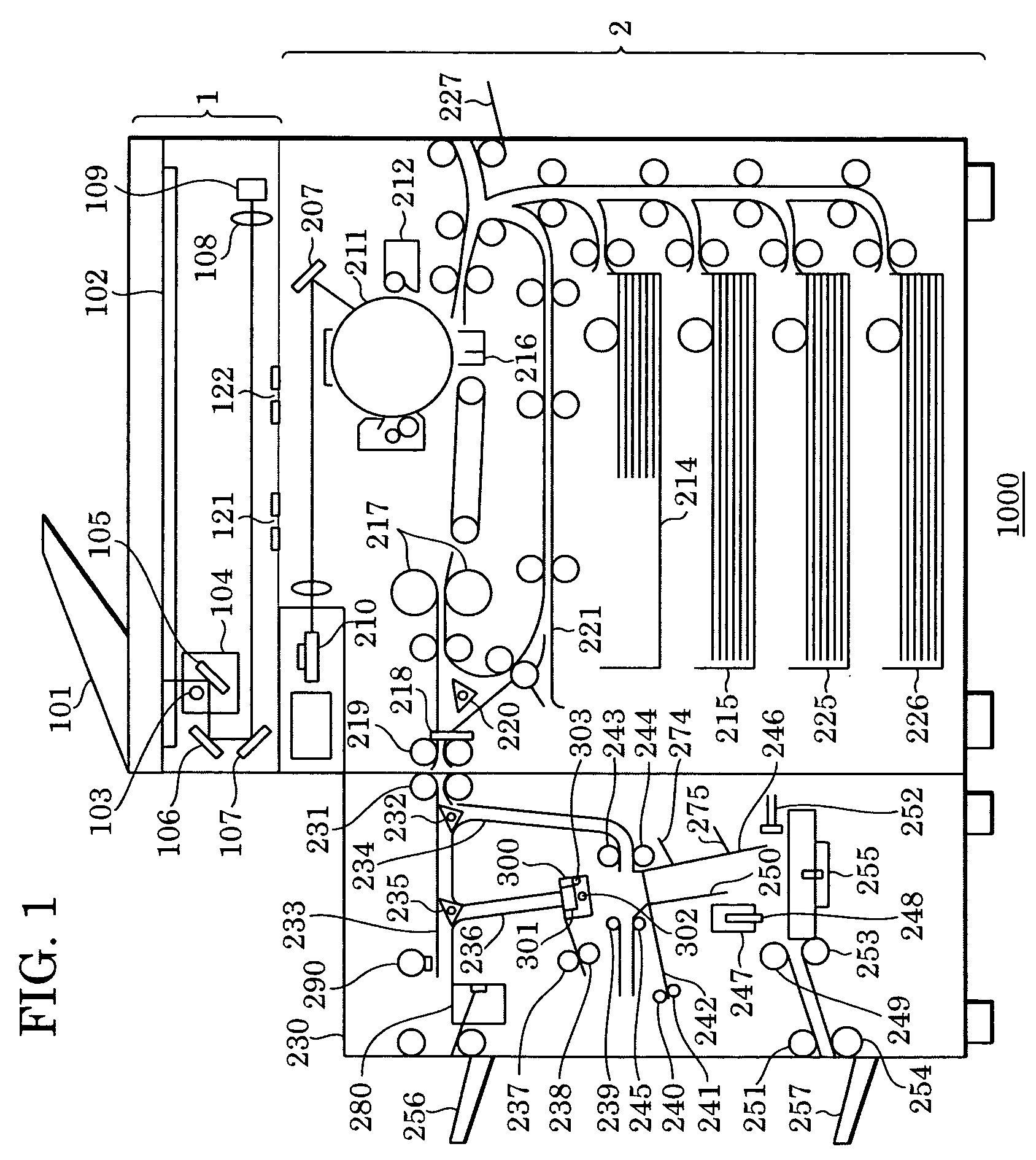
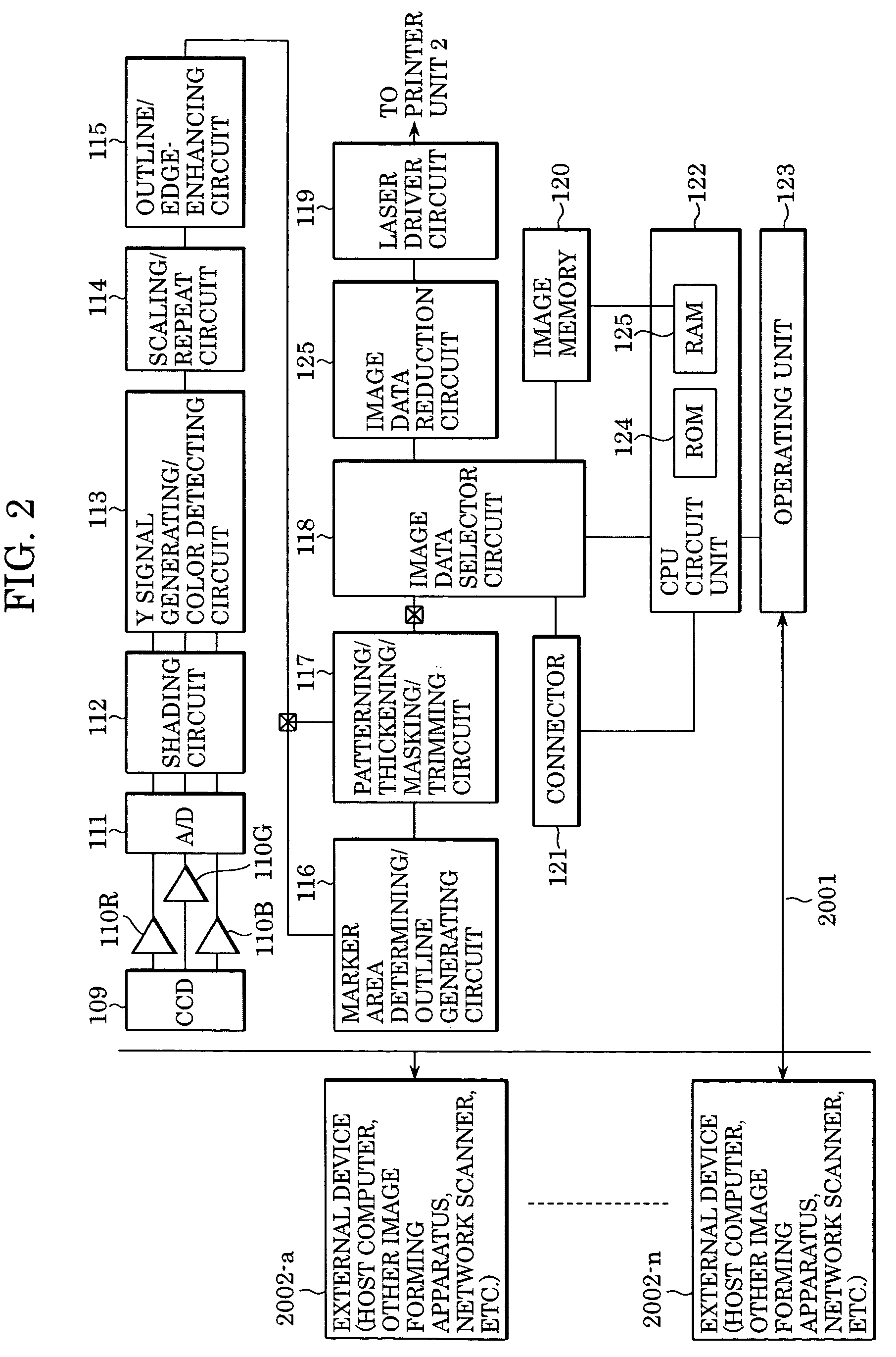
[0068]FIG. 1 is a cross-sectional diagram illustrating the configuration of a photocopier (digital multi-function apparatus) to which can be applied an image forming apparatus (image forming system) according to a first embodiment of the present invention.

[0069]As shown in FIG. 1, the image forming apparatus (also referred to as “image forming system”) 1000 according to the present invention has a reader unit 1 and a printer unit 2. The system 1000 further has a bookbinding unit 230, as an example of a sheet processing device (also called a “finisher”) for subjecting sheets from the image forming apparatus main unit to various types of sheet processes (e.g., a case binding process, a pad binding process, a trimming process, a stapling process, a punching process, a shifted sheet discharge process, and so forth). The following is a description of the configuration and actions of the reader unit 1. The configuration and actions of the printer unit 2 and of the bookbinding unit (also c...

first example

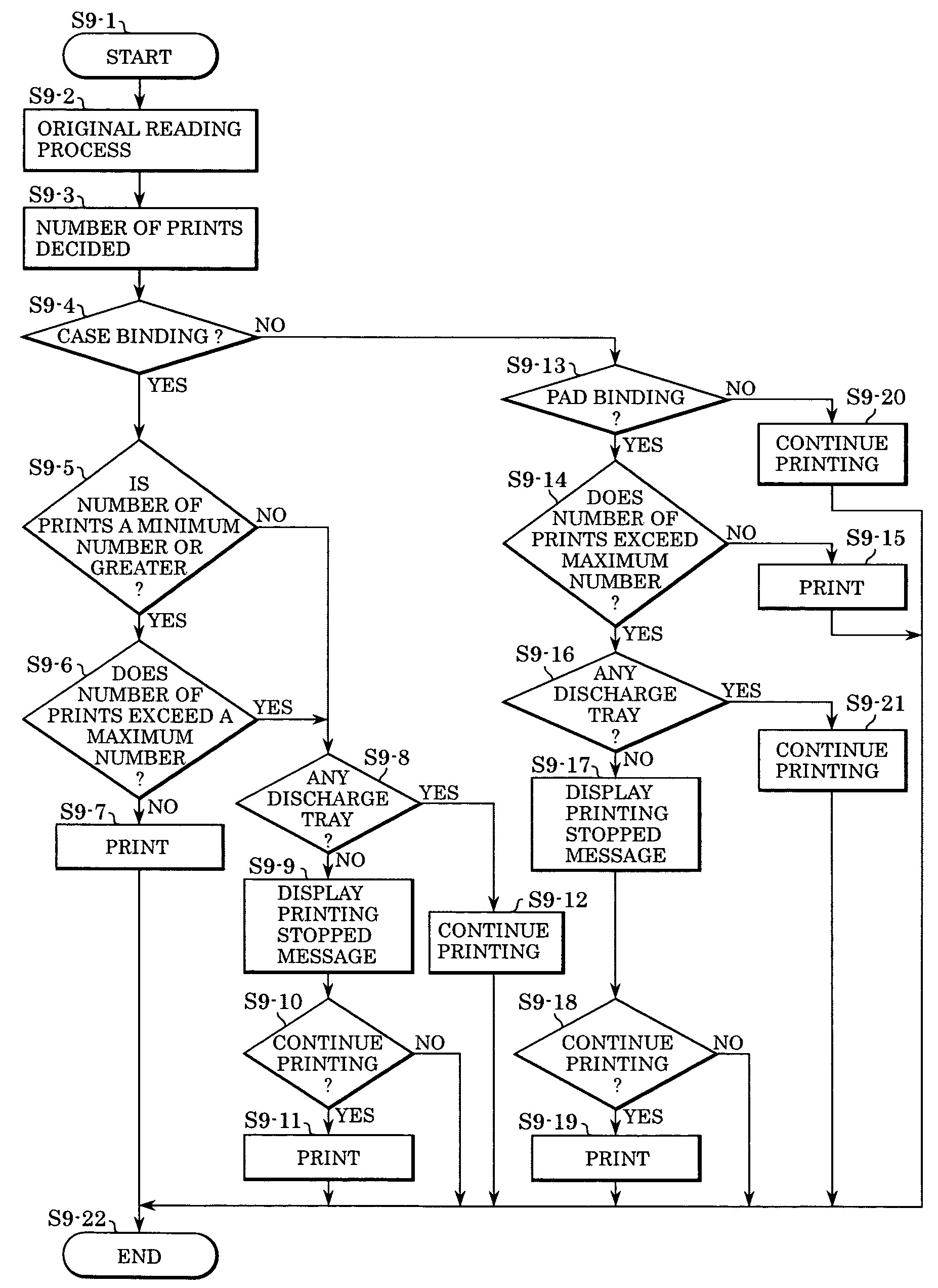
[0137]The CPU circuit unit 122 executes a process for confirming whether or not the total number of sheets used in a job to be processed, regarding which an output condition has been set by the user, is greater than a first predetermined number of sheets (hereafter referred to as “first determination process”). Based on the determination results, whether or not to execute the gluing process for the sheets of the job is decided.

[0138]For example, in the event that a job to be processed is found to be a job using sheets of a number greater than the first predetermined number of sheets as a result of executing the above-describe determination processing, execution of both the case binding process and the pad binding process is inhibited. That is to say, in this case, the CPU circuit unit 122 inhibits both of the sheet gluing process modes.

second example

[0139]In this example, a second predetermined number of sheets is used besides the first predetermined number of sheets as a threshold value. The second predetermined number of sheets is a value smaller than the first predetermined number of sheets. Let us say here that the first predetermined number of sheets is 150 sheets, and the second predetermined number of sheets is 10 sheets, for example. With such a configuration, the CPU circuit unit 122 executes a process for confirming whether or not the total number of sheets used in a job to be processed, regarding which an output condition has been set by the user, is smaller than the second predetermined number of sheets (hereafter referred to as “second determination process”). Based on the determination results, whether or not to execute the gluing process for the sheets of the job is decided.

[0140]For example, in the event that a job to be processed is found to be a job using sheets of a number smaller than the second predetermine...


PUM


Abstract

An image forming system has an image forming apparatus which has a printing unit which can perform a printing process of data of a storage unit which can store data of a plurality of jobs and which has a conveying unit which can convey a sheet from the print unit to a sheet processing device which can perform sheet processing, including at least a gluing process, for sheets from the printing unit, the system comprising: a controller adapted to permit a predetermined process related to the gluing process when the job to be processed is a job which meets a predetermined condition, and to inhibit the predetermined process related to the gluing process when the job to be processed is not a job which meets the predetermined condition, thereby overcoming obstacles to realization of an image forming system capable of a gluing process.

Description

BACKGROUND OF THE INVENTION[0001]1. Field of the Invention[0002]The present invention relates to an image forming apparatus, and more particularly relates to an image forming system having a sheet processing device which performs glue-binding, and to a control method, a recording medium, and a program of the same, and so forth.[0003]2. Description of the Related Art[0004]In recent years, digital multi-function apparatuses having binding printing (pamphlet printing) capabilities using imposition functions with digital image processing have been realized, and now, sheet processing devices which perform saddle-stitching in the process of pamphlet printing are being proposed.[0005]Although the extent of processing which can be realized with such sheet processing devices having saddle-stitching functions is limited to simple bookbinding processing at the present, it is likely that in the future, there will be demand for bookbinding processing at a much higher level, such as glue-binding ...

Claims


Application Information

Patent Timeline
Patent Type & Authority Patents(United States)
IPC IPC(8): G03G15/00B41J29/38B41J29/00B42C19/02B65H37/04G03G21/00H04N1/00
CPCB42C19/02B42P2261/04H04N2201/0094
Inventor ASAI, HIDEHIKOUSHIYAMA, KAZUHIKO
Owner CANON KK
Why Eureka
Try Eureka