Shaft feedback sensor error detection

a technology of shaft feedback and error detection, applied in the direction of speed measurement using gyroscopic effects, liquid/fluent solid measurement, instruments, etc., can solve the problems of periodic speed error (“tach ripple”), erratic performance of control system based on the sensed quantity, and inaccurate measuremen

a technology of shaft feedback and error detection, applied in the direction of speed measurement using gyroscopic effects, liquid/fluent solid measurement, instruments, etc., can solve the problems of periodic speed error (“tach ripple”), erratic performance of control system based on the sensed quantity, and inaccurate measuremen

US7263453B1Active Publication Date: 2007-08-28DEKA PROD LLP

Image

  • Shaft feedback sensor error detection
  • Shaft feedback sensor error detection
  • Shaft feedback sensor error detection

Examples


Embodiment Construction

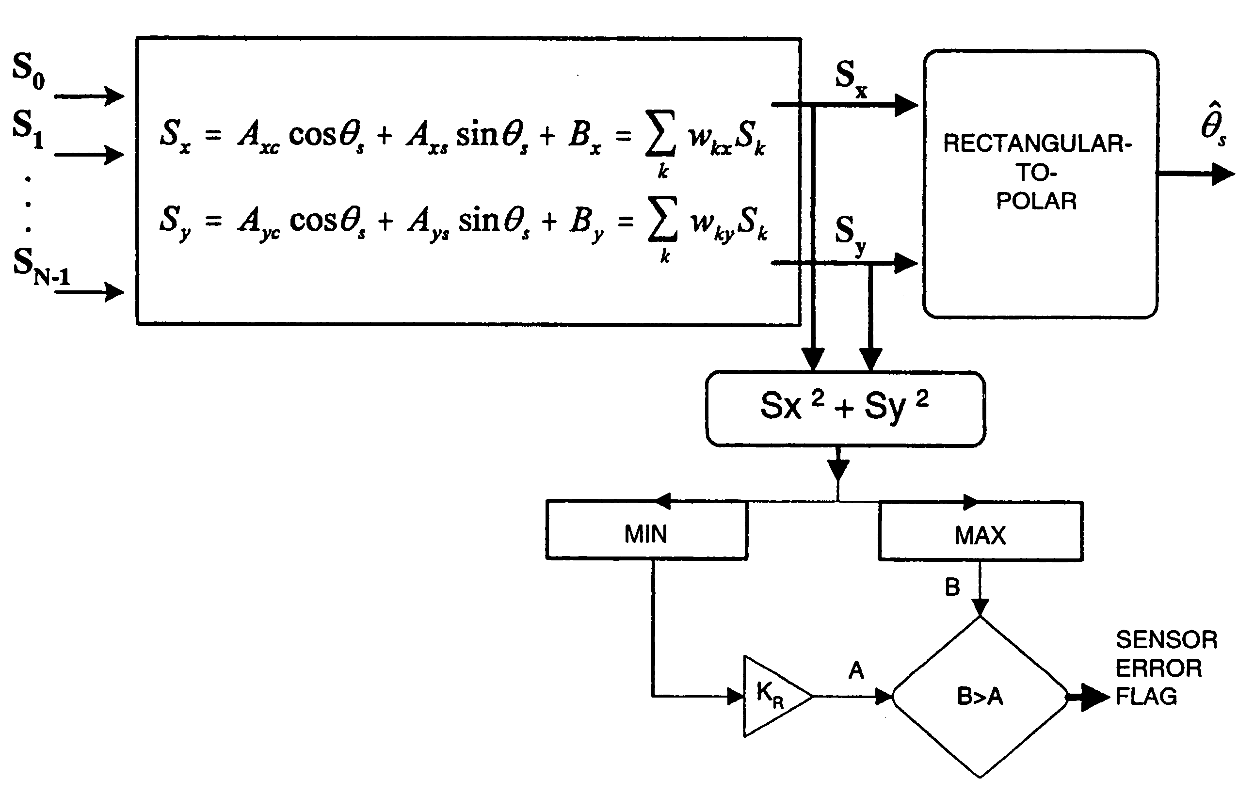
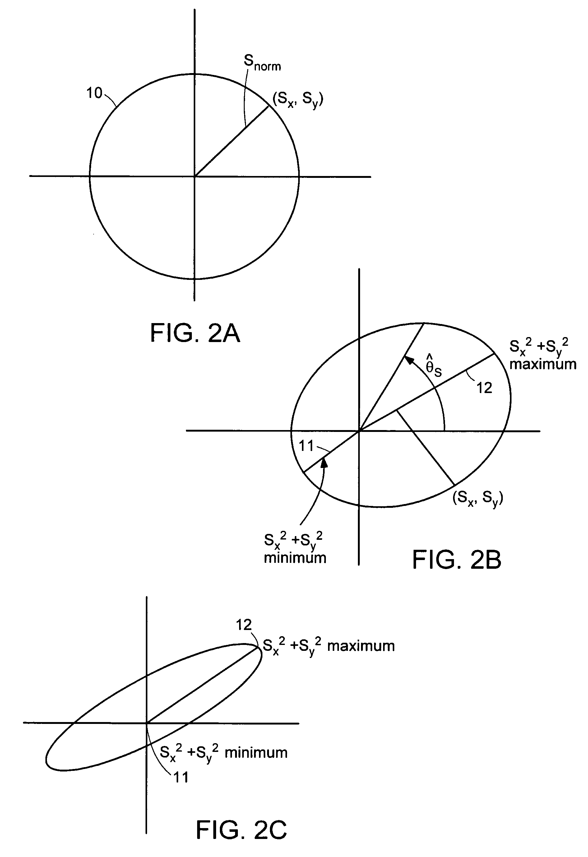
[0025]The apparatus and methods provided in accordance with embodiments of the present invention provide for extraction of a polar coordinate from a set of sensor signals of known phase relationship between, or among, them. Referring to FIG. 2A, the locus, in the two-dimensional plane, of quadrature signals, Sx and Sy, is depicted by curve 10, which is a circle in the ideal case that Sx and Sy represent true quadrature components and that gain amplitudes A1 and A2 are preferably balanced. Polar angle {circumflex over (θ)}s represents an estimate of the true sensor angle θs. The square modulus Sx2+Sy2 represents the square of the instantaneous radius vector from the origin to locus 10. In the ideal case, it maintains a constant value. The square modulus is an example of a norm, referred to generally as Snorm, that is defined over vectors in a space (in this case, two-dimensional), and other norms may also be employed, within the scope of the present invention.

[0026]In a non-ideal ins...


PUM


Abstract

Methods and apparatus for detecting a sensor angle error in a system in which a measured quantity is determined on the basis of a phase of a signal. A signal derived from the measurement of multiple sensors is ascribed to a vector in a two-dimensional space, and a norm is calculated characterizing that vector. A value is calculated characterizing variation of that norm over a specified period of time and that value is compared with a threshold in order to identify a sensor fault.

Description

[0001]The present application claims the benefit of priority from U.S. Provisional Application Ser. No. 60 / 537,837, filed Jan. 21, 2004, which is incorporated herein by reference.TECHNICAL FIELD[0002]The present invention pertains to error detection in systems, such as sensor systems, in which certain signals bear a fixed phase relationship to each other.BACKGROUND ART[0003]A class of sensors, including, for example, position sensors (rotary or linear), or optical interferometers (including Sagnac-Effect gyroscopes, for example), derive a measure of a sensed quantity, such as rotation angle, based on the phase of a periodic envelope of a modulated waveform, shown in FIG. 1, where the modulated waveform is a higher-frequency excitation ‘carrier.’ The phase may be derived by sensing two quadrature components of the demodulated waveform. For analog measured signals of the form,Sxm=A cos θs cos ωet Sym=A sin θs cos ωet′, where ωe is the angular frequency of the excitation signal, the de...

Claims


Application Information

Patent Timeline
28 Aug 2007
Publication
US7263453B1
IPC
G01D18/00
CPC
G01D5/00; G01D5/24457
Inventors
GANSLER, MICHAEL THOMAS; KAUFMAN, MICHAEL FIELD