Magnetically levitated high-speed spindle for shaping irregular surfaces

a high-speed spindle and spindle body technology, which is applied in the direction of turning machines, turning machine accessories, reaming tools, etc., can solve the problems of low yield tolerance variation less than 5 microns, special cutting edge of tools, and non-circular hole shapes which can be produced, etc., to achieve improved precision, greater stability, and higher rotation speed

Inactive Publication Date: 2007-09-04
FEDERAL MOGUL WORLD WIDE
View PDF25 Cites 37 Cited by
  • Summary
  • Abstract
  • Description
  • Claims
  • Application Information

AI Technical Summary

Benefits of technology

[0009]According to a second aspect of the invention, a magnetically levitated high speed spindle assembly is provided for forming a non-circular hole in a workpiece. The assembly comprises an elongated spindle extending along an axial axis between a rear end and a shaping end. A shaping tool extends radially outwardly from the spindle adjacent the shaping end and terminates in a localized cutting edge. A first magnetic bearing cluster supports the spindle proximate the shaping end for magnetically levitated rotation about the axial axis. A second magnetic bearing cluster, spaced from the first magnetic bearing cluster, supports the spindle remote from the shaping end for magnetically levitated rotation about the axial axis. A radial bearing controller is provided for independently controlling the first and second magnetic bearing clusters to adjust the radial position of the axial axis during magnetically levitated rotation of the spindle and move the shaping end in a predetermined non-circular orbital path so that the high speed cutting edge will form a correspondingly shaped non-circular hole in the workpiece. According to this aspect of the invention, a cutting edge controller is provided for maintaining a continuous tilt angle between the cutting edge and the orbital path. The tilt angle comprises an optimal cutting angle defined by the angle between the radius extending from the axial axis to the cutting edge and the tangent line to any point along the orbital path whereby the non-circular hole can be shaped with improved precision and the assembly can operate at higher rotational speed while providing greater spindle stability.
[0011]According to yet another aspect of the invention, a method for magnetically levitating a high speed spindle assembly in contemplated. The method is practiced for forming a non-circular hole in a workpiece and comprises the steps of forming a cutting edge on a shaping tool, affixing the shaping tool to one end of the spindle having an axial axis such that the cutting edge is positioned radially outwardly from the axial axis, establishing a magnetic levitation field about a first region of the spindle proximate the shaping tool for rotation about the axial axis, establishing a magnetic levitation field about a second region of the spindle, spaced from the first region and remote from the shaping tool, rotating the spindle within the first and second magnetic levitation field without the axial axis and adjusting the radial position of the axial axis at the first and second regions during rotation of the spindle by varying the first and second magnetic levitation fields to thereby move the cutting edge in a predetermined non-circular orbital path to form the non-circular hole in the workpiece. The improvement comprises maintaining the continuous tilt angle between the cutting edge and the orbital path so that the non-circular hold can be shaped with improved precision and the spindle can operate at higher rotation speeds and with greater stability. The tilt angle comprises an optimal cutting angle defined by the angle between a radius extending from the axial axis to the cutting edge and the tangent line to any point along the non-circular orbital path.
[0012]The hole forming assembly and method according to the subject invention overcomes the disadvantages and shortcomings of the prior art by expanding the available range of hole shapes and configurations, particularly in a three-dimensional sense, which can be formed with great accuracy at high speeds.

Problems solved by technology

For example, the non-circular hole shapes which can be produced, particularly in 3 dimensions, is especially limited.
And further, the ability to precisely control the position of the tool cutting edge and thereby yield tolerance variations less than 5 microns is not reliable.

Method used


Image

  • Magnetically levitated high-speed spindle for shaping irregular surfaces
  • Magnetically levitated high-speed spindle for shaping irregular surfaces
  • Magnetically levitated high-speed spindle for shaping irregular surfaces

Examples


Embodiment Construction

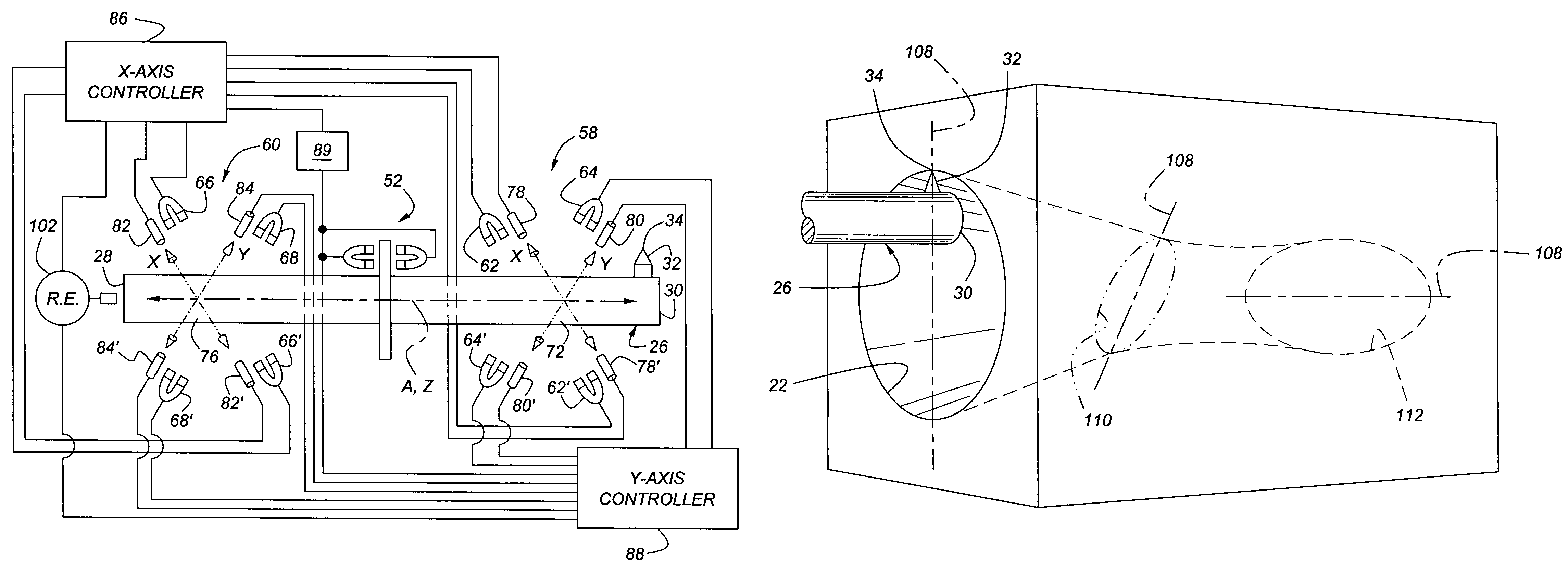
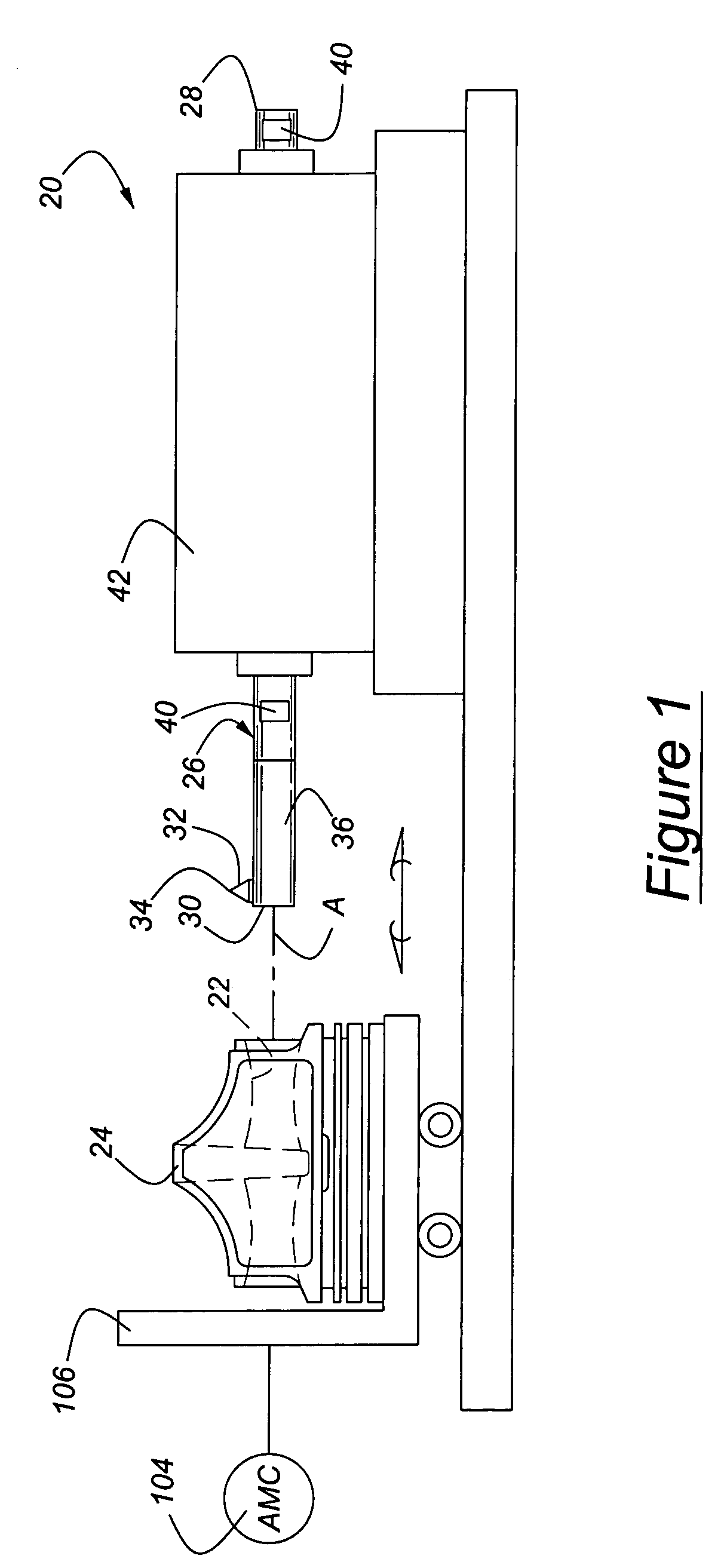
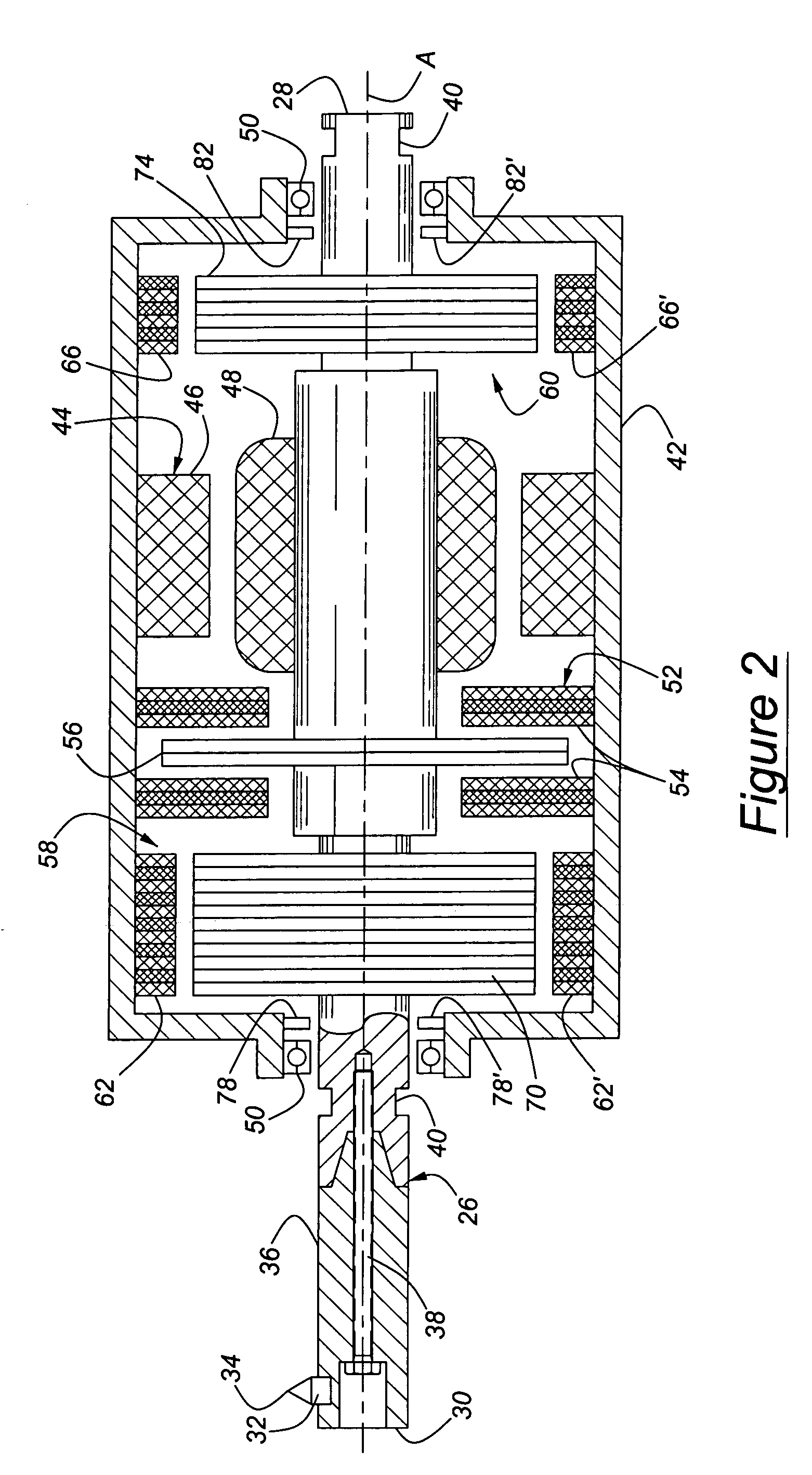
[0025]Referring to the Figures, wherein like numbers indicate like or corresponding parts throughout the several views, a magnetically levitated high-speed spindle assembly is generally shown at 20 in FIGS. 1 and 2. The spindle assembly 20 is of the type for forming non-circular holes 22 in a workpiece 24. In FIG. 1, the workpiece 24 is shown for purposes of example only comprising a piston for an internal combustion engine. The non-circular hole 22 is illustrated as the pin hole for containing the wrist pin (not shown) as is well known in the art. The workpeice 24, however, may comprise any component and is not limited to pistons, engines or even automotive applications. Rather, any field of endeavor in which a non-circular hole 22 of high precision tolerance may be applicable.

[0026]The assembly20 includes a rigid shaft-like spindle, generally indicated at 26 extending along an axial axis A between a rear end 28 and a shaping end 30. A shaping tool 32 extends radially outwardly fro...


PUM

PropertyMeasurementUnit
angleaaaaaaaaaa
tilt angleaaaaaaaaaa
speedaaaaaaaaaa

Abstract

A magnetically levitated high-speed spindle assembly (20) is provided for forming non-circular holes (22) in workpieces (24) or non-circular surfaces on pins. The non-circular holes (22) can be formed with dimensionally varying axial trajectories at high speeds and with great accuracy. This is accomplished by supporting a rotating spindle (26) between first (58) and second (60) magnetic bearing clusters and independently controlling these bearing clusters (58, 60) to move a shaping tool (32) at the end of the spindle (26) in a predetermined orbital path (B). A multiple input-multiple output control strategy is used to control spindle (26) movements in the X and Y axes. The tilt angle between the cutting edge (34) of the shaping tool (32) and the orbital path (B) is maintained perpendicular under this multiple input-multiple output control of the magnetic bearing clusters (58, 60) to further improve shaping precision and spindle (26) stability during high-speed operations.

Description

[0001]This application claims priority to U.S. Provisional Application Ser. No. 60 / 547,891, filed Feb. 26, 2004.BACKGROUND OF THE INVENTION[0002]1. Technical Field[0003]This invention relates generally to magnetically levitated high-speed spindle assemblies for shaping non-circular surfaces, and more particularly toward such an assembly for forming a non-circular hole in a workpiece.[0004]2. Related Art[0005]Some production applications require the formation of non-circular holes. For example, in the manufacture of pistons for an internal combustion engine, the so-called pin holes formed for the wrist, or gudgeon pin often have a slight trumpet shape opening toward the center for accommodating flex in the wrist pin. Additionally, this trumpet shape of the pin hole is optimally designed with a slight ovality to further account for distortion in the wrist pin as it moves through its various cycles. This trumpet shape and non-circular cross section of the pin hole must be formed to exa...

Claims


Application Information

Patent Timeline
Patent Type & Authority Patents(United States)
IPC IPC(8): B23B3/00B23B5/36B23Q1/48B23Q5/10
CPCB23B5/36B23Q1/4876F16C32/0489B23Q5/10B23B2260/0045B23B2270/38B23B2270/58Y10T408/85Y10T409/309352Y10T82/122Y10T82/10F16C2322/39B23B5/00
Inventor BISCHOF, KENNETH R.ZDEBLICK, WILLIAM J.
Owner FEDERAL MOGUL WORLD WIDE
Why Eureka
Try Eureka